Back in 1978, an oscilloscope was an exotic piece of gear for most homebrewers. We expect they were even more rare in private hands behind the iron curtain, and [Thomas Scherrer] shows us a Soviet X1-7B combination oscilloscope and spectrum analyzer (he thinks, at least, it is a spectrum analyzer) that he got working.
The Soviet scope is clearly different with its Cyrillic front panel. Luckily, Google Translate was up to the task of decoding a picture of the device. However, the differences aren’t just cosmetic. The scope also has a very interesting rotating bezel around the round CRT. You can see a video of the 8.2 kg scope below.
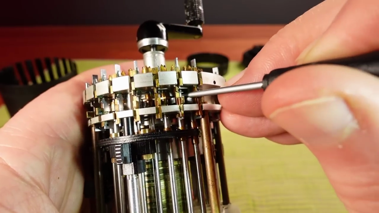
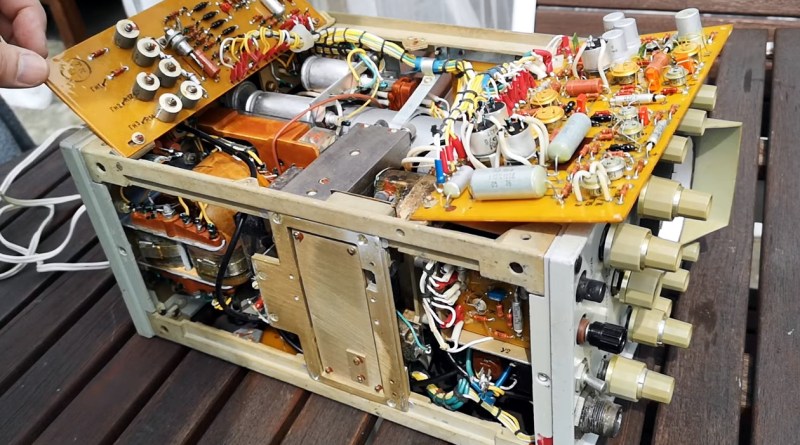
A quick look inside looks pretty conventional for a scope of that era that used all transistors in the circuitry. The rotating bezel, though, also controls something that looks like a big mechanical switch and cavity or, perhaps, a big mechanical variable component of some kind.
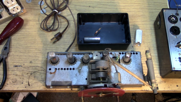
Satisfied that the insides were in reasonable shape, [Thomas] was ready to try turning it on. We want to say it went well, but… there was censored audio, along with a loud noise, right after it was plugged in. Troubleshooting centered on what was producing a burned smell, but a quick examination didn’t turn up anything obvious, despite being localized to the power circuitry. The fuse didn’t blow, oddly, and — even more puzzling — the unit was off when plugged in!
It turns out the input power filter leaked to the chassis. Since he had a ground on the chassis, that explained the failure, and while it was annoying, it was better than getting a shock with a hot chassis. The second plug in went better.
It finally did work, at least somewhat, although he never explored some of the odd features the scope appears to have. We love the old boat anchor scopes but don’t see many Soviet instruments, at least not those of us on this side of the Atlantic.
We do see a few Soviet-era computers now and again. As for the fuse not blowing, it was shorted before the fuse, but apparently, fuses don’t always blow when you expect them to, anyway.
Continue reading “Examining Test Gear From Behind The Iron Curtain” →