With temperatures dropping in the Northern Hemisphere, this is the time of year when many people start processing firewood for the coming winter months. For the city folks, that means chopping a tree into logs, and then splitting those logs into something small enough to fit in your wood stove. You can do it all with hand tools, but if you’ve got big enough logs, a powered splitter is a worthy investment.
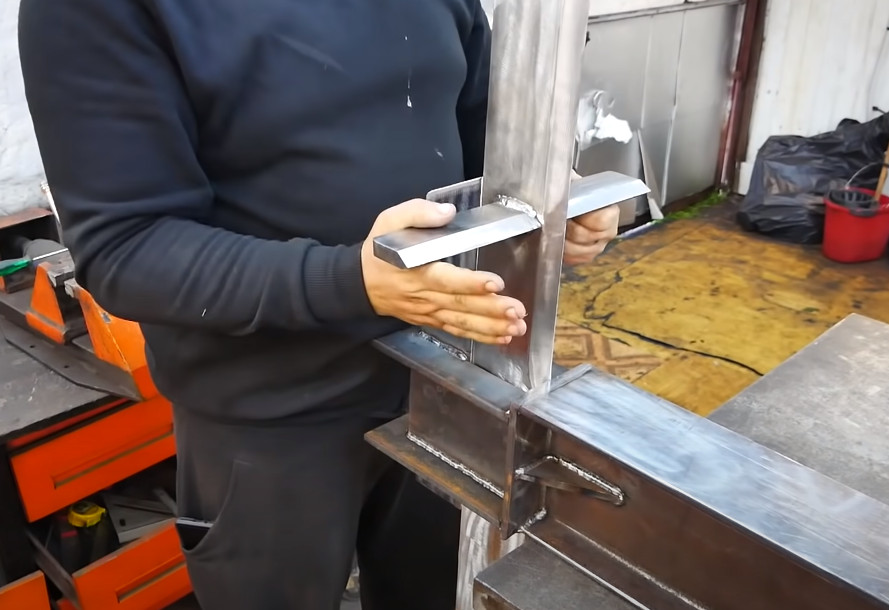
Unless of course you’re like [Workshop From Scratch], in which case you can craft a powerful splitter from random bits of steel you’ve got laying around your impeccably outfitted shop. Given the incredible forces some parts of the splitter will be exposed to, he really takes his time on this build to make sure everything is bulked up. Add in his legendary attention to detail, and you’ll be watching this one for awhile. Not that we’re complaining.
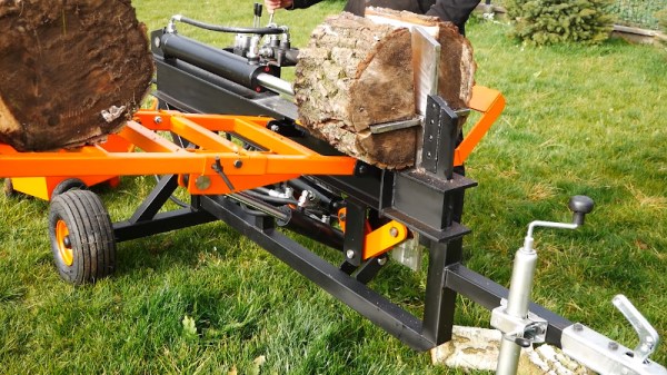
Early on it seemed like [Workshop From Scratch] was putting together a fairly simple log splitter, which in the most basic form is nothing more complex than a hydraulic cylinder pushing a log against a triangular piece of metal. But then he starts layering on the special features, such as the small hydraulic cylinder that can raise and lower the splitter’s fearsome looking blade.
There’s also the ladder-like feeder mechanism, which prevents the user from having to lift the log onto the machine manually; just stop the log between the rungs, and let the hydraulics raise the ramp and send the log rolling towards the machine’s hungry maw.
In short, this splitter may be a DIY project, but it’s just as strong and well built as anything on the commercial market. In fact, it’s probably an improvement over what you’d be able to find a the big box retailer. Which shouldn’t come as surprise if you’ve seen some of his previous work.
Continue reading “Building A Heavy-Duty Log Splitter, One Piece At A Time”