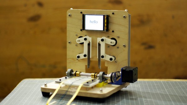
Over the last year or so, we’ve been checking in on the progress [Andrew Consroe] has been making with his incredible CNC scroll saw project. While we were already impressed with his first prototype version, he somehow manages to keep pushing the envelope forward with each new upgrade, and we’re always excited when one of his progress reports hits the inbox.
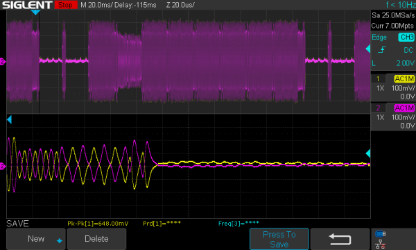
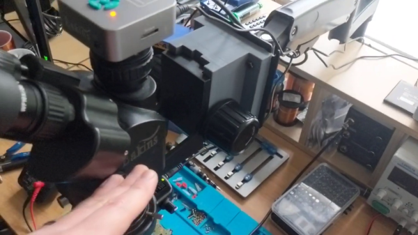
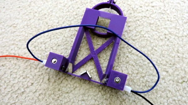
Recently he’s been struggling with the fact that the considerable flexing of the scroll saw’s ultra-thin blade introduces positional errors while cutting. To combat this, he’s developed an ingenious sensor that can track the movement of the blade in two dimensions without actually touching it. Utilizing the Raspberry Pi HQ camera, a 3D printed framework, and some precisely placed mirrors, [Andrew] says his optical sensor is able to determine the blade’s position to within 10 microns.
 In the video below [Andrew] goes over how his “Split Vision Periscope” works, complete with some ray traced simulations of what the Pi camera actually sees when it looks through the device. After experimenting with different lighting setups, the final optical configuration presents the camera with two different perspectives of the saw blade set on a black background. That makes it relatively easy to pick out the blade using computer vision, and turn that into positional information.
The periscope arrangement is particularly advantageous here as it allows the camera and lens to be placed under the work surface and well away from the actual cutting, though we’re interested in seeing how it fares against the dust and debris that will inevitably be produced as the saw cuts. While he hit all of his design goals, [Andrew] does note that his mirrors do leave some room for improvement; but considering he hand cut them out of old hard drive platters we think the results are more than acceptable.
An incredible amount of progress has been made since the first time we saw the CNC scroll saw, and we’re eager to see this new sensor fully integrated into the next version of [Andrew]’s impressive long-term project.
Continue reading “Optical Sensor Keeps Eye On Wandering Saw Blade”