If you’ve ever had the good fortune — or, after a shop mishap, the misfortune — to see the insides of a dial indicator, you’ll know the workings of these shop essentials resemble nothing so much as those of a fine Swiss watch. The pinions, gears, and springs within transmit the slightest movement of the instrument’s plunger to a series of dials, making even the tiniest of differences easy to spot.
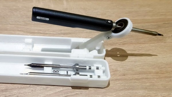
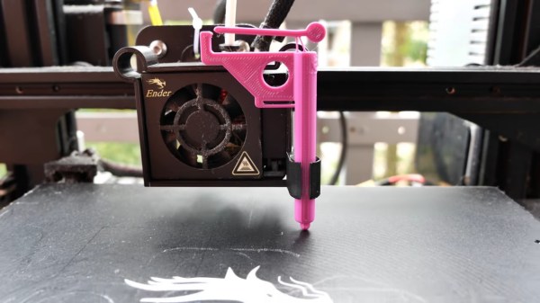
Not every useful dial indicator needs to have those mechanical guts, nor even a dial for that matter. This compliant mechanism 3D-printed dial-free indicator is perfect for a lot of simple tasks, including the bed leveling chores that [SunShine] designed it for. Rather than print a bunch of gears and assemble them, [SunShine] chose to print the plunger, a fine set of flexible linkage arms, and a long lever arm to act as a needle. The needle is attached to a flexible fulcrum, which is part of the barrel that houses the plunger. Slight movements of the plunger within the barrel push or pull on the needle, amplifying them into an easily read deflection. When attached to the head of a 3D-printer and scanned over the bed, it’s easy to see even the slightest variation in height and make the corresponding adjustments. Check it out in the video below.
We’re big fans of compliant mechanisms, seeing them in everything from robot arms and legs to thrust vectoring for an RC plane. This might look like something from a cereal box, and it certainly doesn’t have the lasting power of a Starrett or Mitutoyo, but then again it costs essentially nothing, and we like that too.
Continue reading “No Assembly Required For This Compliant Mechanism Dial Indicator”