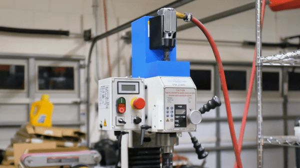
Imagine the scenario: you’re spending some quality time in the shop with your daughter, teaching her the basics while trying to get some actual work done. You’re ripping some stock on your cheap table saw when your padiwan accidentally hooks the power cord with her foot and pulls out the plug. You have a brief chat about shop safety and ask her to plug it back in. She stoops to pick up the cord and plugs it back in while her hand is on the table! Before you can stop the unfolding tragedy, the saw roars to life, scaring the hell out of everyone but thankfully doing no damage.
If that seems strangely specific it’s because it really happened, and my daughter was scared out of the shop for months by it. I’ll leave it to your imagination what was scared out of me by the event. Had I only known about no-voltage release switches, or NVRs, I might have been able to avoid that near-tragedy. [Gosforth Handyman] has a video explaining NVRs that’s worth watching by anyone who plugs in anything that can spin, cut, slice, dice, and potentially mutilate. NVRs, sometimes also called magnetic contactors, do exactly what the name implies: they switch a supply current on and off, but automatically switch to an open condition if the supply voltage fails.
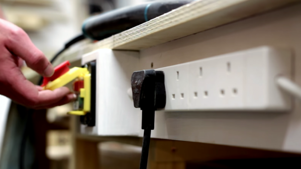
Big power tools like table saws and mills should have them built in to prevent a dangerous restart condition if the supply drops, but little tools like routers and drills can still do a lot of damage if they power back up while switched on. [Gosforth] built a fail-safe power strip for his shop from a commercial NVR, and I’d say it’s a great idea that’s worth considering. Amazon has a variety of NVRs that don’t cost much, at least compared to the cost of losing a hand.
True, an NVR power strip wouldn’t have helped me with that cheap table saw of yore, but it’s still a good idea to put some NVR circuits in your shop. Trust me, it only takes a second’s inattention to turn a fun day in the shop into a well-deserved dressing down by an angry mother. Or worse.
Continue reading “Save Fingers, Save Lives With A No-Voltage Release For The Shop”