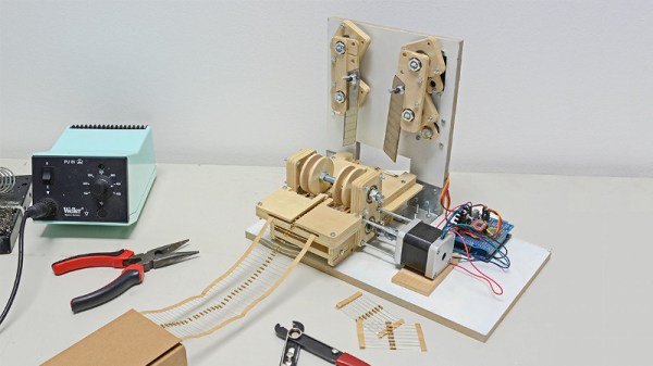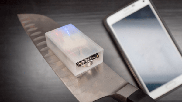
Few things are as frustrating in the kitchen as a dull knife. [Becky] and her chef friend collaborated to build a Bluetooth module to tell you when you are sharpening a knife at the optimum angle. That might sound a little specialized, but the problem boils down to one that is common enough in a lot of situations: how do you tell your exact orientation while in motion? That is, with the knife moving rapidly back and forth over the sharpening stone, how can you measure the angle of the blade reliably?
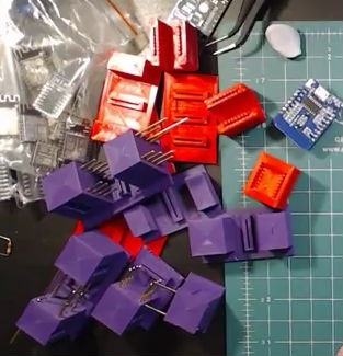
Looking for a challenge, [Becky’s] first attempt was to just use an accelerometer. It worked, but it wasn’t very precise. Her final answer turned out to be a full inertial measurement unit — the BNO055 — that combines an accelerometer, a magnetometer, and a gyroscope along with enough smarts to fuse the data into actual position data.