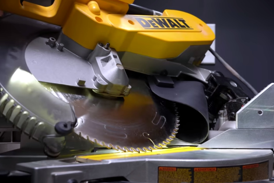
Let’s be honest. When it comes to operating miter saws, these tools kick dust out the back like a spray paint can. Most of us have accepted this quirk as-is, but not [Inspire Woodcraft] who’s on a mission to achieve near perfect dust collection. And he nearly has it. With a budget dust collection setup, he’s able to eliminate over 90% of the dust from his cuts, and others who’ve adopted his setup can vouch for his results.
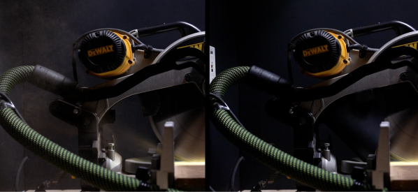
The solution comes in two pieces. First, he focuses on creating a new dust shroud or “boot” for collecting dust through the vacuum hookup on the back of the saw. What’s key here is that this dust boot is made from squishy silicone, enabling it to flare outwards and spread out as the saw travels downward into the material. It’s clear that [Inspire Woodcraft] has gone through dozens of material and shape iterations, but the result is sturdy enough to stay open with the vacuum running through the back hose attachment.
 With the dust nearly perfectly funneled from the back, the second tweak focuses on rerouting stray dust away from the table and directly into this boot. [Inspire Woodcraft] later noticed that dust collection from the bottom of his miter saw simply didn’t exist, so dust would accumulate at his feet.
His solution? To create a second shroud that fits under the throat plate that takes sawdust once destined for the ground and ejects it backwards and straight into the dust collection boot.
Altogether, this setup solves a long-existing problem with a handful of commodity parts and a few 3D prints. [Inspire Woodcraft] has also chronicled his journey in such detail where you too could recreate his solution from the video. But if you’re feeling lazy, and you’re lucky enough to own the same Dewalt DW716 or DWS716 model miter saws, you can simply snag a kit from his website.
If all this talk of miter saws has your reaching for a screwdriver to see what modified mayhem you can unleash with yours, look no further than this LED hack that adds a shadow line to your cuts.
Continue reading “Squishy Miter Saw Shroud Spares You The Sneezy Bits”