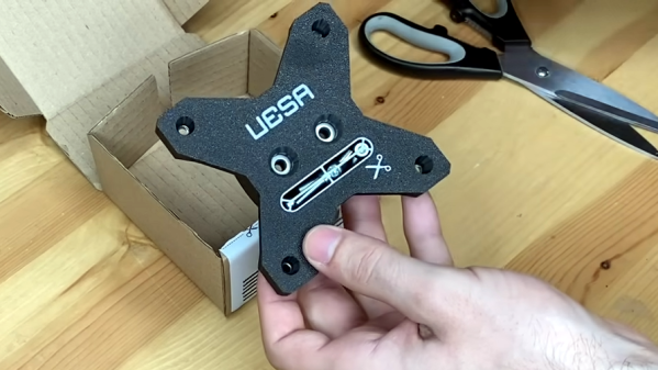
Print Your Own Drill Guide Without A Linear Bearing

Typically we often don’t cover paid products here on Hackaday, but we couldn’t help but be impressed with this 3D printed drill guide from [USSA]. While you’ll need to pay the toll to access the STL files and plans, there’s an excellent video showing a bit of magic behind the curtain that you can check out free of charge. There are several interesting insights and some great techniques put into this design that anyone could take and apply to their own project.

First, what is a drill guide? Many of us don’t have the luxury of a full-sized drill press, so we have to make do with a hand drill. There are various jigs and tricks to get straighter holes, but it can be frustrating to mark out threaded screw inserts with great precision only to discover all the inserts are at an angle and the circuit board won’t fit. A drill guide ensures holes are plunged straight up and down and at a reliable depth.

[USSA] starts by showing the node-based CAD that makes up the design (a program called Grasshopper). As he assembled it, simple nuts and screws held it together. But rather than clamp two separate pieces together, the screws compress the single plastic with a clever slot in the side to allow the plastic to flex. Several 3D printed jigs were used for assembling the bearing shaft. Ultimately the results look quite impressive, and it’s an inspiration for our own printed projects.

Continue reading “Print Your Own Drill Guide Without A Linear Bearing”

Beautiful Inductors, Now Not Such A Lost Art

As ferrite technology has progressed into a mastery of magnetic permeability, the size of inductors has gone down to the point at which they are now fairly nondescript components. There was a time though when inductors could be beautiful creations of interleaving layers of copper wire in large air-cored inductors, achieved through clever winding techniques. It’s something that’s attracted the attention of [Brett], who’s produced a machine capable of producing something close to the originals.

Part of the write-up is an investigation of the history, these coils were once present even at the consumer level but are now the preserve of only a few highly secretive companies. They are still worth pursuing though because they can deliver the high “Q” factor that is demanded in a high quality tuned circuit. The rest of the write-up dives in detail into the design of the wire feeder, and the Arduino motor control of the project. There should be enough there for any other experimenters to try their hands at layered inductors, so perhaps we’ll see this lost art make a comeback.

Custom coils are a regular requirement for anything from radios, to musical instruments, to switching power supplies, so it’s not surprising that quite a few projects featuring them have made it here. One of the more unusual of late has been one that winds toroids.

A Home Made Sewing Machine May Be The Only One

The sewing machine is a tool that many of us will have somewhere around our workshop. Concealed within it lies an intricate and fascinating mechanism. Some of us may have peered inside, but very few indeed of us will have gone to the effort of building our own. In case you had ever wondered whether it was possible, [Fraens] has done just that, with what he claims may be the only entirely homemade sewing machine on the Internet.

If you’ve ever studied the history of sewing machines you’ll notice that it bears a striking resemblance to some of the earliest commercial machines, with a relatively short reach and an entirely open construction. The main chassis appears to be laser-cut acrylic while all the fittings are 3D-printed, with machined brass bushes and aluminum rods for the other metal parts. The design utilizes a hand crank, but is also pictured with a DC motor. It makes for a fascinating illustration of how sewing machines work. Sadly we can’t see any design file links (Update: He’s contacted us to tell us they’re now on Thingiverse.), so you might have to be inventive if that’s the way you want to build your own. Take a look at it in the video below the break.

Fancy a sewing machine but don’t fancy making your own? We’ve got the guide for that, and for filling the rest of your textile bench.

Continue reading “A Home Made Sewing Machine May Be The Only One”

A Handy Tester For A Mountain Of PS/2 Keybords

The hacking life is not without its challenges, and chief among these is the tendency to always be in acquisition mode. When we come across a great deal on bulk equipment, or see a chance to rescue some obscure gear from the e-waste stream, we generally pounce on it, regardless of the advisability.

We imagine this is why [Nathan] ended up with a hoard of PS/2 keyboards. Seriously, there are like thousands of the things. And rather than lug a computer to them for testing, [Nathan] put together this handy Arduino-based portable tester to see which keyboards still have some life left in them. The video below goes into detail on the build, but the basics are pretty simple — an Arduino, a 16×2 LCD display, and a few bits and bobs to run it off a LiPo pack and charge it up. Plus, of course, a PS/2 jack to plug in a keyboard and power it up. Interestingly, the 16×2 display is an old Parallax unit, from the days when RadioShack still existed and sold their stuff. That required a little effort to get it working with the Arduino, but in the end it works like a charm — plug in a keyboard and whatever you type shows up on the screen.

Of course, it’s hard to look at something like this, and that mountain of keyboards in the background, and not scheme up ways to really automate the whole test process. Perhaps an old 3D printer with a stylus mounted where the hot end would go could press each key in turn while the tester output is recorded — something like this Wordle-bot, but on a keyboard scale. That kind of goes against [Nathan]’s portability goal, but it’s still fun to think about.

Continue reading “A Handy Tester For A Mountain Of PS/2 Keybords”

photo of the CNC controller, with the PLCC socket for the CPU, surrounded by driver ICs

Old CNC Brain Swapped With An Arduino

[Sebastian] and [Stefan Shütz] had a ISEL EP1090 CNC machine at home, sitting unused, and they decided to bring it to life. With pretty good mechanical specs, this CNC looked promising – alas, it was severely constrained by its controller. The built-in CPU’s software was severely outdated, had subpar algorithms for motor driving programmed in, and communication with the CNC was limited because the proprietary ISEL communications protocol that isn’t spoken by other devices.The two brothers removed the CPU from its PLCC socket, and went on to wiring a grbl-fueled Arduino into the controller box.

The interposer PCB, with an extra 74HC245 buffer on itThey reverse-engineered the motor driver connections – those go through a 74HC245 buffer between the original CPU and the drivers. Initially, they put an Arduino inside the control box of the CNC and it fit nicely, but it turned out the Arduino’s CPU would restart every time the spindle spun up – apparently, EMC would rear its head. So, they placed the Arduino out of the box, and used two CAT7 cables to wire up the motor and endstop signals to it.

For tapping into these signals, they took the 74HC245 out of its socket, and made an interposer from two small protoboards and some pin headers – letting them connect to the STEP and DIR lines without soldering wires into the original PCB. There’s extensive documentation, GRBL settings, and more pictures in their GitHub repo, too – in case you have a similar CNC and would like to learn about upgrading its controller board!

After this remake, the CNC starts up without hassles. Now, the brothers shall CNC on! Often, making an old CNC machine work is indeed that easy, and old controller retrofits have been a staple of ours. You can indeed use an Arduino, one of the various pre-made controller boards like Gerbil or TinyG, or even a Raspberry Pi – whatever helps you bridge the divide between you and a piece of desktop machinery you ought to start tinkering with.

Mis-captured signal transitions shown on the screen of the LA104, with problematic parts circled in red.

When Your Logic Analyzer Can’t Tell Good And Bad Signals Apart

[Avian] has picked up a Miniware LA104 – a small battery-powered logic analyzer with builtin protocol decoders. Such analyzers are handy tools for when you quickly need to see what really is happening with a certain signal, and they’re cheap enough to be sacrificial when it comes to risky repairs. Sadly, he stumbled upon a peculiar problem – the analyzer would show the signal glitching every now and then, even at very low bitrates. Even more surprisingly, the glitches didn’t occur in the signal traces when exported and viewed on a laptop.

A Pulseview window showing that the problem is not present in the exported capturesHe dug into the problem, as [Avian] does. Going through the problem-ridden capture files helped him realize that the glitch would always happen when one of the signal edges would be delayed by a few microseconds relative to other signal edges — a regular occurrence when it comes to digital logic. This seems to stem from compression being used by the FPGA-powered “capture samples and send them” part of the analyzer. This bug only relates to the signal as it’s being displayed on the analyzer’s screen, and turned out that while most of this analyzer’s interface is drawn by the STM32 CPU, the trace drawing part specifically was done by the FPGA using a separate LCD interface.

It would appear Miniware didn’t do enough testing, and it’s impossible to distinguish a good signal from a faulty one when using a LA104 – arguably, the primary function of a logic analyzer. In the best of Miniware traditions, going as far as being hostile to open-source firmware at times, the FPGA bistream source code is proprietary. Thus, this bug is not something we can easily fix ourselves, unless Miniware steps up and releases a gateware update. Until then, if you bought a LA104, you can’t rely on the signal it shows on the screen.

When it comes to Miniware problems, we’ve recently covered a Miniware tweezer repair, requiring a redesign of the shell originally held together with copious amount of glue. At times, it feels like there’s something in common between glue-filled unrepairable gadgets and faulty proprietary firmware. If this bug ruins the LA104 for you, hey, at least you can reflash it to work as an electronics interfacing multitool.

Pulling A Chainsaw With Gravity

[Flowering Elbow] had a large ash log that needed to be milled. He had his chainsaw and shared an excellent technique for an easier cut. After cutting down a tree, letting it dry for a season, and then hauling it to your saw site, you’re ready to cut. However, cutting a humongous tree with a chainsaw is an enormous task. A few hacks make it better, like tilting your log slightly downhill, so the chainsaw flows downhill or using a jig to keep the cut straight. Some use a winch system to drag the jig along to assist, so it’s not just pure manpower. The problem is that a winch will exert more force if the saw hits a knot or challenging section. So you would want to slow down and let the saw work through the area.

[Flowering Elbow] uses a pulley and offcut from the log and hangs it from a tree. The log drops as the cut progresses and exerts a constant force. This means that the saw can slow down during challenging sections and take the time it needs, extending the blade’s life. There are other excellent tips in the video, and combined with his earlier chainsaw mill jig, you’ll be set to mill up logs with nothing but a chainsaw and some ingenuity.

Video after the break.

Continue reading “Pulling A Chainsaw With Gravity”