Flexible Grip For Hammer Made With 3D Printing Pen

When it comes to putting a flexible grip on a tool, you might reach for a self-fusing silicone tape or other similar product. However, [Potent Printables] has discovered you can easily create a flexible grip using a 3D-printing pen and some flex filament.

In this case, a hammer first gets a layer of blue painters tape wrapped around its wooden handle. This serves as a base layer to promote good adhesion. A simple paper template was then printed as a guide for creating the graphics on the flexible grip. Flexible filament was fed through the 3D pen, with the red and black details of the graphics printed first. Then, white flex filament was used to make the rest of the flexible grip. A wood burning tool was then used to smooth out the first layer of flex filament, before a second layer was added on top.

The result is a flexible white grip on the hammer which is stuck fast, likely due to shrinkage as the plastic cooled after printing. We’ve seen some other creative grips made with 3D printing before, too. Video after the break.

Continue reading “Flexible Grip For Hammer Made With 3D Printing Pen”

Nanovolt Meter Requires Careful Design For Accuracy’s Sake

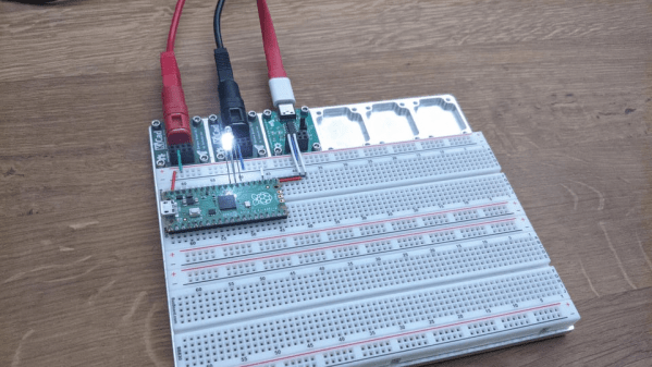
Measuring voltages is fairly straightforward most of the time. Simply grab any old cheap multimeter, hook up the probes, and read off the answer. If, however, you need to measure very tiny voltages, the problem gets more complex. [Jaromir-Sukuba] designed a nanovoltmeter specifically to deal with this difficult case.

The nanovoltmeter is exactly what it sounds like: a voltmeter that is sensitive and stable enough to measure and report voltages on the scale of nanovolts. Having a tool that can do this reliably can be very useful when it comes to measuring very small resistances or working with ever-so-slight differential voltages. Continue reading “Nanovolt Meter Requires Careful Design For Accuracy’s Sake”

A home-made vacuum pickup tool

Hackaday Prize 2022: Salvaged Pumps And Hoses Make A Neat Vacuum Pickup Tool

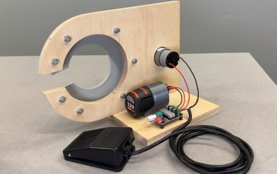
Anyone who’s ever assembled a PCB full of tiny SMD parts will have found that tweezers are not always the best tool when it comes to accurate positioning. Thin, flat components like microcontrollers can be awkward to pick up securely, while small resistors and capacitors have a tendency of snapping out of your tweezers’ grip and flying off into the sunset (or your carpet). Vacuum pickup tools can be a great help, but the most convenient models, with an electric air pump and a foot switch, can be a bit expensive. [sjm4306] shows that it doesn’t have to be that way: he built his “VacPen” mostly from reused components.

At the heart of the project is a little vacuum pump with a pen-like device hooked up to it through a flexible hose. The tip of the pen holds a pickup nozzle that came from a cheap manual pick and place tool. Both the pump and pen were salvaged from some gas analysis instrument that [sjm4306] tore apart a long time ago; the pen is especially convenient since it comes with a built-in brush-like filter that can trap any debris or tiny parts that might be accidentally swallowed.

The VacPen controller is housed inside a neat 3D printed enclosure that holds a custom PCB with an ATtiny microcontroller. The pump can be operated either through a foot switch, or by pressing on the touch-sensitive pad on top of the enclosure. [sjm4306] made this by soldering a wire to a copper penny and sticking it on the inside of the lid: simple, effective and cheap.

As you can see in the video embedded below, the VacPen is perfectly capable of picking up any kind of SMD component, and just as importantly, immediately releasing it at the desired moment. If you’re new to SMD technology, we can recommend this tutorial by [Bil Herd] that covers vacuum tweezers as well. If you’re more into automating vacuum pickup tools, this cool robot might be of your interest.

Continue reading “Hackaday Prize 2022: Salvaged Pumps And Hoses Make A Neat Vacuum Pickup Tool”

Caulking Gun Becomes Useful Press Tool For Fuel Line Fittings

The simple caulking gun is really useful when you’re working on some bathroom repairs or squirting construction adhesives about the place. However, with a few simple mods, it can become a great help in the mechanic’s workshop too.

It’s a great tool for cleanly pushing fittings into nylon fuel line.

This build consists of a series of 3D-printed parts that can readily be adapted to a garden-variety caulking gun. First up are a pair of fuel line clamps which are fastened together with nuts and bolts, The nylon fuel line is inserted between these, and the bolts are tightened up to hold the line firmly in place at the end of the caulking gun. The fitting to be installed into the line is then placed on the caulking gun’s plunger. It’s then a simple matter of pulling the trigger on the caulking gun to slowly press the fitting into the nylon line.

It’s a great hack which creates a useful linear press with just a few cents of PETG filament. If you find yourself doing a one-off fuel line job on a modern car, this could be just the tool you need. Parts are available on Thingiverse for those eager to print their own. The design is made for 3/8ths inch line, but could readily be modified or recreated to suit other diameters.

3D-printed tools can be useful in all kinds of ways, even in heavy-duty applications like press tooling. It often doesn’t have the same longevity of traditional metal tooling, but for small one-off jobs, the price saving is often more important than the hardiness of the tooling itself. If you’ve whipped up some great 3D-printed tools of your own, don’t hesitate to drop us a line!

Theory, Practice, And Ducted Fans

About a year ago, [Wyman’s Workshop] needed a fan. But not just a regular-old fan, no sir. A ducted fan. You know, those fancy fan designs where the stationary shroud is so close to the moving fan blades that there’s essentially no gap, and a huge gain in aerodynamic efficiency? At least in theory?

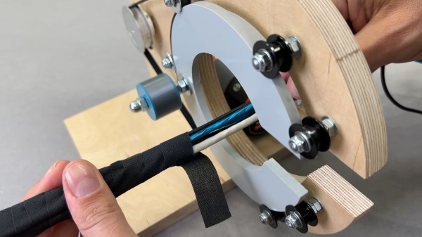
Well, in practice, you can watch how it turned out in this video. (Also embedded below.) If you’re more of a “how-to-build-it” type, you’ll want to check out his build video — there’s lots of gluing 3D prints and woodworking. But we’re just in it for the ducted fan data!

And that’s why we’re writing it up! [Wyman] made a nice thrust-testing rig that the fan can pull on to figure out how much force it put out. And the theory aimed at 652 g of thrust, which was roughly confirmed. And then you get to power: with a 500 watt motor, he ended up producing 47 watts. Spoiler: he’s overloading the motor, even though he used a fairly beefy bench grinder motor.

So he re-did the fan design, from scratch, to better match the motor. And it performed better than the theory said it would. A pleasant surprise, but it meant re-doing the theory, including the full volume of the fan blade, which finally brought theory and practice together. Which then lead him design a whole slew of fan blades and test them out against each other.

He ends the video with a teaser that he’ll show us the results from various inlet profiles and fan cones and such. But the video is a year old, so we’re not holding our breath. Still, if you’re at all interested in fan design, and aren’t afraid of high-school physics, it’s worth your time.

Don’t care about the advantages of ducted fans, but simply want to make your quad look totally awesome?  Have we got the hack for you!

Continue reading “Theory, Practice, And Ducted Fans”

A square PCB with a Raspberry Pi Pico mounted in the middle

Identify Radioactive Samples With This DIY Gamma-Ray Spectrometer

If you’re a radiation enthusiast, chances are you’ve got a Geiger counter lying around somewhere. While Geiger counters are useful to detect the amount of radiation present, and with a few tricks can also distinguish between the three types of radiation (alpha, beta and gamma), they are of limited use in identifying radioactive materials. For that you need a different instrument called a gamma-ray spectrometer.

Spectrometers are usually expensive and complex instruments aimed at radiation professionals. But it doesn’t have to be that way: physics enthusiast [NuclearPhoenix] has designed a hand-held gamma spectrometer that’s easy to assemble and should fit in a hobbyist budget. It outputs spectral plots that you can compare with reference data to identify specific elements.

A PCB with a sensor wrapped in black tape
The scintillator and sensor are wrapped in black tape to block out ambient light.

The heart of the device is a scintillation crystal such as thallium-doped sodium iodide which converts incoming gamma rays into visible light. The resulting flashes are detected by a silicon photomultiplier whose output is amplified and processed before being digitized by a Raspberry Pi Pico’s ADC. The Pico calculates the pulses’ spectrum and generates a plot that can be stored on its on-board flash or downloaded to a computer.

[NuclearPhoenix] wrote a convenient program to help analyze the output data and made all design files open-source. The hardest part to find will be the scintillation crystal, but they do pop up on auction sites like eBay now and then. We’ve featured an Arduino-based gamma spectrometer before; if you’ve always wanted to roll your own scintillators, you can do that too. Continue reading “Identify Radioactive Samples With This DIY Gamma-Ray Spectrometer”

Screenshot of a logic analyzer software, showing the SDA channel being split into three separate traces

I2C Tap Helps Assign Blame For SDA Conflicts

If you’ve ever debugged a misbehaving I2C circuit, you probably know how frustrating it can be. Thankfully [Jim] over at Hackaday.io, has a proto-boardable circuit that can help!

Inter-integrated circuit bus (aka I2C) uses open collector outputs on a two wire interface. Open collector means a device connected to the I2C bus can only pull the bus down to ground. Chips never drive a logic “HIGH” on the wires. When nothing is driving the lines low, a weak resistor pulls the lines up to VCC. This is a good thing, because I2C is also a multidrop bus — meaning many devices can be connected to the bus at the time. Without open collector outputs, one chip could drive a high, while another drives a low – which would create a short circuit, possibly damaging both devices.

Even with all this protection, there can be problems. The SCL and SDA lines in the I2C communication protocol are bidirectional, which means either a controller or a peripheral can pull it low. Sometimes, when tracing I2C communications you’ll need to figure out which part is holding the line low. With many devices sharing the same bus, that can become nigh-impossible. Some folks have tricks with resistors and analog sampling, but the tried and true method of de-soldering and physically lifting chip pins off the bus often comes into play.

[Jim’s] circuit splits SDA signal into controller-side and peripheral-side, helping you make it clear who is to blame for hiccups and stray noise. To do that, he’s using 6N137 optoisolators and LMV393 comparators. [Jim] shared a NapkinCAD schematic with us, meant to be replicate-able in times of dire need. With this design, you can split your I2C bus into four separate channels – controller-side SDA, peripheral-side SDA, combined SDA and SCL. 4 Channels might be a lot for a scope, but this is no problem for today’s cheap logic analyzers.

Continue reading “I2C Tap Helps Assign Blame For SDA Conflicts”