Build An Amazon EC2 Gaming Rig

PC gaming is better than console gaming. Now that we’ve said something controversial enough to meet the comment quota for this post, let’s dig into [Larry]’s Amazon EC2 gaming rig.

A while ago, [Larry] bought a MacBook Air. It’s a great machine for what it is, but it’s not exactly the laptop you want for playing modern AAA games on the go. If you have enough bandwidth and a low enough ping, you can replicated just about everything as an EC2 instance.

[Larry] is using a Windows Server 2012 AMI with a single NVIDIA GRID K520 GPU in his instance. After getting all the security, firewall, and other basic stuff configured, it’s just a matter of installing a specific driver for an NVIDIA Titan. With Steam installed and in-home streaming properly configured it’s time to game.

The performance [Larry] is getting out of this setup is pretty impressive. It’s 60fps, but because he’s streaming all his games to a MacBook Air, he’ll never get 1080p.

If you’re wondering how much this costs, it’s actually not too bad. The first version of [Larry]’s cloud-based gaming system was about $0.54 per hour. For the price of a $1000 battle station, that’s about 1900 hours of gaming, and for the price of a $400 potato, that’s 740 hours of gaming.

Battlezone Played On Vector Display With Hand-Wound Yoke

We’ve been admirers of the work [Eric] and friends have been doing over at TubeTime for years. One of the earliest we can remember is the decatron kitchen timer, and we still tell the story of [Eric] purposely leaving out button debouncing in order to make his vector flappy bird even harder.

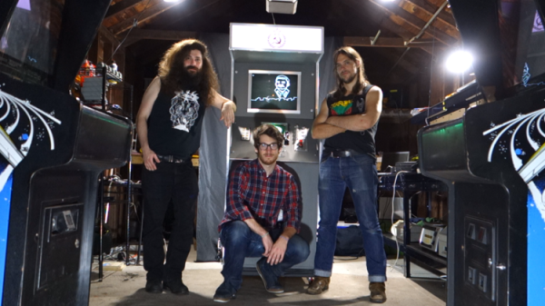
TubeTime is back at it this year and we had the opportunity to speak with them at Bay Area Maker Faire. The group specializes in working with old tube displays and this year’s offering was spectacular in many ways. First off, the software side of things is an emulator running on an STM32 F4 Discovery board. The chips on these boards have a pair of 12-bit DACs which are driving the X and Y of the vector displays. Code to run the original ROMs was ported from existing projects, but the audio for the games was kind of a hack to get working.

This particular display is where things get really fascinating. The tube itself was originally manufactured as test equipment for television repairmen. What’s fascinating about this is that [Eric] had to rewind the deflection yokes himself to get it working again. Luckily he documented quite a bit about his initial research into this process and his experiments to remedy some distortion issues he encountered once it was working.

Make sure to head on over to TubeTime and read their overview of the Battlezone machine. After the break we’ve also embedded a few of our own pictures as well as the interview at BAMF.

Continue reading “Battlezone Played On Vector Display With Hand-Wound Yoke”

Better VGA On The STM32F4

[Cliff] is pushing VGA video out of a microcontroller at 800×600 resolution and 60 frames per second. This microcontroller has no video hardware. Before we get to the technical overview, here’s the very impressive demo.

The microcontroller in question is the STM32F4, a fairly powerful ARM that we’ve seen a lot of use in some pretty interesting applications. We’ve seen 800×600 VGA on the STM32F4 before, with a circles and text demo and the Bitbox console. [Cliff]’s build is much more capable, though; he’s running 800×600 @ 60FPS with an underclocked CPU and most (90%) of the microcontroller’s resources free.

This isn’t just a demo, though; [Cliff] is writing up a complete tutorial for generating VGA on this chip. It begins with an introduction to pushing pixels, and soon he’ll have a walkthrough on timing and his rasterization framework.

Just because [Cliff] has gone through the trouble of putting together these tutorials doesn’t mean you can’t pull out an STM Discovery board and make your own microcontroller video hacks. [Cliff] has an entire library of for graphics to allow others to build snazzy video apps.

Googly Eyes Follow You Around The Room

If you’re looking to build the next creepy Halloween decoration or simply thinking about trying out OpenCV for the first time, this next project will have you covered. [Glen] made a pair of giant googly eyes that follow you around the room using some servos and some very powerful software.

The project was documented in three parts. In Part 1, [Glen] models and builds the eyes themselves, including installing the servo motors that will eventually move them around. The second part involves an Arduino and power supply that will control the servos, and the third part goes over using OpenCV to track faces.

This part of the project is arguably the most interesting if you’re new to OpenCV; [Glen] uses this software package to recognize different faces. From there, the computer picks out the most prominent face and sends commands to the Arduino to move the eyes to the appropriate position. The project goes into great detail, from Arduino code to installing Ubuntu to running OpenCV for the first time!

We’ve featured some of [Glen]’s projects before, like his FPGA-driven LED wall, and it’s good to see he’s still making great things!

Continue reading “Googly Eyes Follow You Around The Room”

Eye-Controlled Wheelchair Advances From Talented Teenage Hackers

[Myrijam Stoetzer] and her friend [Paul Foltin], 14 and 15 years old kids from Duisburg, Germany are working on a eye movement controller wheel chair. They were inspired by the Eyewriter Project which we’ve been following for a long time. Eyewriter was built for Tony Quan a.k.a Tempt1 by his friends. In 2003, Tempt1 was diagnosed with the degenerative nerve disorder ALS  and is now fully paralyzed except for his eyes, but has been able to use the EyeWriter to continue his art.

This is their first big leap moving up from Lego Mindstorms. The eye tracker part consists of a safety glass frame, a regular webcam, and IR SMD LEDs. They removed the IR blocking filter from the webcam to make it work in all lighting conditions. The image processing is handled by an Odroid U3 – a compact, low cost ARM Quad Core SBC capable of running Ubuntu, Android, and other Linux OS systems. They initially tried the Raspberry Pi which managed to do just about 3fps, compared to 13~15fps from the Odroid. The code is written in Python and uses OpenCV libraries. They are learning Python on the go. An Arduino is used to control the motor via an H-bridge controller, and also to calibrate the eye tracker. Potentiometers connected to the Arduino’s analog ports allow adjusting the tracker to individual requirements.

The web cam video stream is filtered to obtain the pupil position, and this is compared to four presets for forward, reverse, left and right. The presets can be adjusted using the potentiometers. An enable switch, manually activated at present is used to ensure the wheel chair moves only when commanded. Their plan is to later replace this switch with tongue activation or maybe cheek muscle twitch detection.

First tests were on a small mockup robotic platform. After winning a local competition, they bought a second-hand wheel chair and started all over again. This time, they tried the Raspberry Pi 2 model B, and it was able to work at about 8~9fps. Not as well as the Odroid, but at half the cost, it seemed like a workable solution since their aim is to make it as cheap as possible. They would appreciate receiving any help to improve the performance – maybe improving their code or utilising all the four cores more efficiently. For the bigger wheelchair, they used recycled car windshield wiper motors and some relays to switch them. They also used a 3D printer to print an enclosure for the camera and wheels to help turn the wheelchair. Further details are also available on [Myrijam]’s blog. They documented their build (German, pdf) and have their sights set on the German National Science Fair. The team is working on English translation of the documentation and will release all design files and source code under a CC by NC license soon.

Colorizer For ZX81 Clone

[danjovic] is a vintage computer enthusiast and has several old computers in his collection. Among them are a couple of TK-85 units – a ZX81 clone manufactured by Microdigital Eletronica in Brazil. The TK-85 outputs a monochrome video output. And when [danjovic] acquired a SyncMaster 510 computer monitor, he went about building a circuit to “colorise” the output from the ZX81 clone (Portuguese translation).

The SyncMaster 510 supports 15kHz RGB video refresh rate, so he thought it ought to be easy to hook it up to the TK-85, which internally has the video and composite sync signals available. So, if he could lower the amplitude of the video signal to 0.7Vpp, using resistors, and connect this signal to one of the primary colors on the monitor, for example green, then the screen should have black characters with a green background.

DSCN5584-thumbBefore he could do any of this, he first had to debug and fix the TK-85 which seemed to be having several age related issues. After swapping out several deteriorating IC sockets, he was able to get it running. He soldered wires directly to one of the logic chips that had the video and sync signals present on them, along with the +5V and GND connections and hooked them up to a breadboard. He then tested his circuit consisting of the TTL multiplexer, DIP switches and resistors. This worked, but not as expected, and after some digging around, he deduced that it was due to the lack of the back porch in the video signal. From Wikipedia, “The back porch is the portion of each scan line between the end (rising edge) of the horizontal sync pulse and the start of active video. It is used to restore the black level (300 mV.) reference in analog video. In signal processing terms, it compensates for the fall time and settling time following the sync pulse.”

To implement the back porch, he referred to an older hack he had come across that involved solving a similar problem in the ZX81. Eventually, it was easily implemented by an RC filter and a diode. With this done, he was now able to select any RGB value for foreground and background colors. Finally, he built a little PCB to house the multiplexer, DIP switches and level shifting resistors. For those interested, he’s also documented his restoration of the TK-85 over a four-part blog post.

Raspberry Pis And A Video Triptych

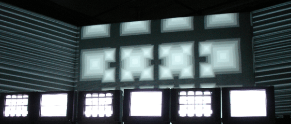
A filmmaker friend of [Thomas] mentioned that she would like to display a triptych at the 2015 Venice Art Walk. This is no ordinary triptych with a frame for three pictures – this is a video triptych, with three displays each showing a different video, and everything running in sync. Sounds like a cool engineering challenge, huh?

The electronics used in the build were three Raspberry Pi 2s and a trio of HDMI displays. Power is provided by a 12V, 10A switching supply with 5V stepdown converters for the Pis. The chassis is a bunch of aluminum bars and U channel encased in an extremely well made arts and crafts style frame. So far, nothing out of the ordinary.

Putting three monitors and three Pis in a frame isn’t the hard part of this build; getting three different displays all showing different videos is. For this, [Thomas] networked the Pis through an Ethernet hub, got the videos to play independently on a RAM disk with omxplayer. One of the Raspberry Pis serves as the master, commanding the slaves to start, stop, and rewind the video on cue. According to [Thomas], it’s a somewhat hacky solution with a bunch of sleep statements at the beginning of the script to allow the boot processes to finish. It’s a beautiful build, though, and if you ever need to command multiple monitors to display the same thing, this is how you do it.