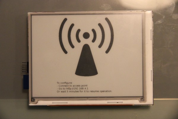
The idea of a pirate box is pretty simple. All you need is a tiny Linux system with a WiFi adapter, a bit of storage space, and the software that will allow anyone to upload a few files to the server and an interface that will let anyone on the network download those files. In practice, though, a pirate box is a mess of wires and power adapters – not the pocketable device a WiFi file sharing box should be.
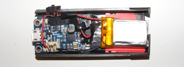
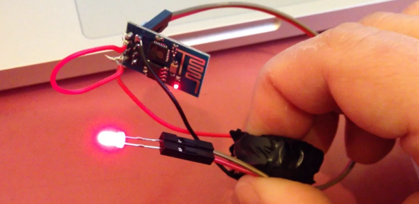
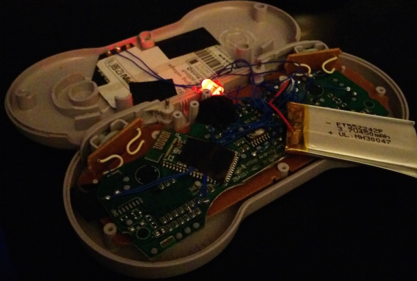
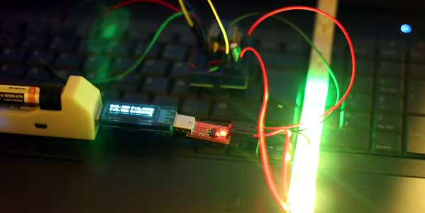
[Chris] came up with a much smaller file sharing beacon. It’s not based on a router; instead, [Chris]’ build uses an ez Share WiFi microSD adapter. It’s a device meant to push pics taken by a digital camera up to the Internet, but by configuring the software just so, up to five users can connect to the adapter and pull files down from a microSD card. The build only requires putting power to the correct pins. A LiPo battery and charge controller takes care of this problem.
There are a few shortcomings to this project – [Chris] doesn’t know how to upload files to the device. Maybe someone sufficiently clever can figure out how to make that work. Still, if you’re ever in a situation where you’d like to share some files with people in the same building, this is the device you need.
Thanks [Jake] for the tip.
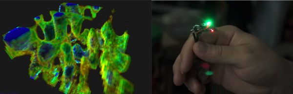
 Armed with this information, [Charles] went for broke and mounted his ESP8266 on a large gantry style mill. He took several long exposure videos of a 360x360x180mm area. The videos were extracted into layers. The whole data set could then be visualized with Voxeltastic, [Charles’] own HTML5/WEBGL based render engine. The results were