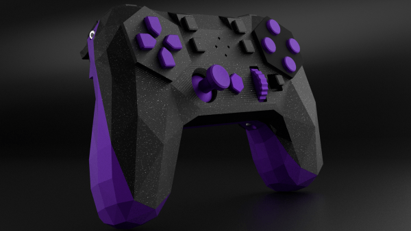
Input Labs’ mission is to produce open-source Creative Commons hardware and software for creating gaming controllers that can be adapted to anyone. Alpakka is their current take on a generic controller, looking similar to a modern Xbox or PlayStation controller but with quite a few differences. The 3D printed casing has a low-poly count, angular feel to it, but if you don’t like that you can tweak that in blender to just how you want it. Alpakka emulates a standard USB-attached keyboard, mouse, and Xinput gamepad in parallel so should just work out of the box for both Linux and Windows PC platforms. The firmware includes some built-in game profiles, which can be selected on the controller.
The dual D-pads, augmented with an analog stick, is not an unusual arrangement, but what is a bit special is the inventive dual-gyro sensor arrangement –which when used in conjunction with a touch-sensitive pad — emulates a mouse input. Rest your thumb on the right-hand directional pad and the mouse moves, or else it stays fixed, kind of like lifting a mouse off the pad to re-center it.
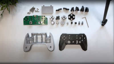
The wired-only controller is based around a Raspberry Pi Pico, which has plenty of resources for this type of application giving a fast 250 Hz update rate. But to handle no fewer than nineteen button inputs, as well as a scroll wheel, directional switch, and that analog stick, the Pico doesn’t have enough I/O, needing a pair of NXP PCAL6416A I2C IO expanders to deal with it.
The PCB design is done with KiCAD, using a simple 3D printed stand to hold the PCB flat and the through-hole components in place while soldering. Other than a few QFN packages which might be a problem for some people, there is nothing tricky about hand-soldering this design.
We’ve been seeing custom game controllers as long as we’ve been hacking, here’s an interesting take on the mouse-integration theme. If you’re comfortable rolling the hardware side of things, but the firmware is a sticking point, then perhaps look no further than this neat RP2040 firmware project.
Continue reading “Alpakka: A Creative Commons Game Controller”