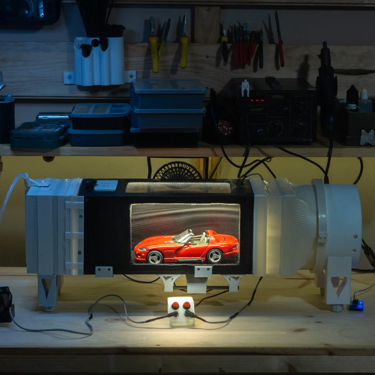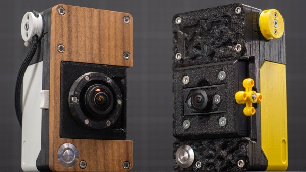
Like many others, [volzo] loves playing with photography in a playful and experimental way. Oddball lenses, vintage elements, and building from kits is what that world looks like. But that kind of stuff is really the domain of film cameras, or at least it was until [volzo] created his Digital Toy Camera design. The result? A self-built, lomography-friendly digital camera that allows for all kinds of weird and wonderful attachments and photo shenanigans.
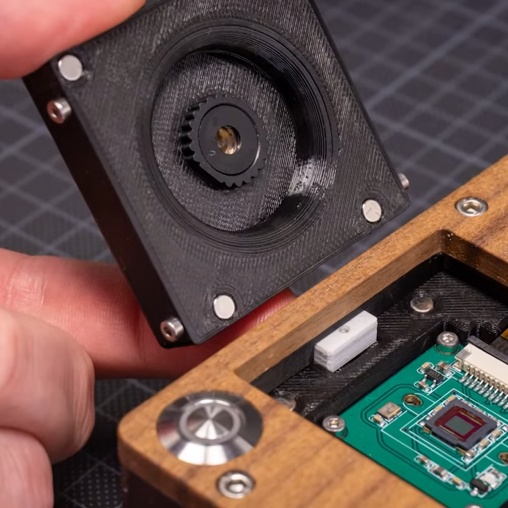
To make a DIY digital camera that allowed that kind of play, the first problem [volzo] had to solve was deciding on an image sensor. It turns out that sourcing image sensors as an individual is a pretty cumbersome process, and even if successful, one still needs to write a driver and create things from the ground up. So, the guts of [volzo]’s creations use the Raspberry Pi and camera sensor ecosystem and M12 lenses, a decision that allows him to focus on the rest of the camera.
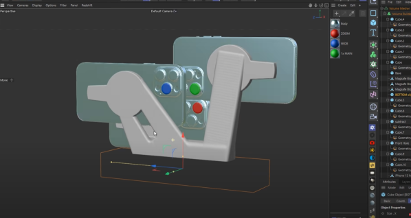
3D printing, a bit of CNC machining, and some clever design yields a “toy” camera: simple, inexpensive, and enabling one to take a playful and experimental approach to photography. The design files are available on GitHub, and there are some neat elements to the design. Magnetic mounts allow for easy swapping of lens assemblies, and a M12 x 0.75 tap cuts perfect threads into 3D-printed pieces for M12 lenses.
Heat-set inserts also provide robust fastening that can hold up to disassembly and re-assembly (and don’t miss that our own [Joshua Vasquez] has shared how best to design for and use heat-set inserts.)
[volzo] has a fantastic video to accompany his project; give it a watch (embedded below, under the page break) and see if you don’t come away with some inspiration of your own.
Continue reading “Digital “Toy” Camera, Made For Tilt-Shift And Other Analog-Like Experimenting”