Learn To Play Guitar, Digitally

Learning to play a musical instrument takes a major time commitment. If you happened to be stuck inside your home at any point in the last two years, though, you may have had the opportunity that [Dmitriy] had to pick up a guitar and learn to play. Rather than stick with a traditional guitar, though, [Dmitriy] opted to build his own digital guitar which is packed with all kinds of features you won’t find in any Fender or Gibson.

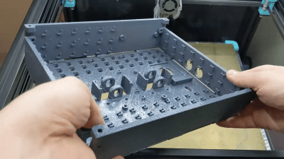
The physical body of this unique instrument is entirely designed by [Dmitriy] out of 3D printed parts, and uses capacitive touch sensors for each of the notes on what would have been the guitar’s fretboard. The strings are also replaced with a set of six switches that can be strummed like a regular guitar, and are used to register when to play a note. After a few prototypes, everything was wired onto a custom PCB. The software side of this project is impressive as well; it involved creating custom firmware to register all of the button presses and transmit the information to a MIDI controller so that the guitar can communicate digitally with anything that supports MIDI.

To finish off the project, [Dmitriy] also added a wireless device as well as some other bonus features like an accelerometer, which can be used to augment the sound of the guitar in any way he can think of to program them. It’s one of the most innovative guitars we’ve seen since the prototype Noli smart guitar was unveiled last year, and this one is also on its way from prototype to market right now.

Continue reading “Learn To Play Guitar, Digitally”

Split Flap Display Tells Us The Word

LED and LCD displays are a technological marvel. They’ve brought the price of televisions and monitors down to unheard-of levels since the days of CRTs, but this upside arguably comes with an aesthetic cost. When everything is covered in bland computer screens, the world tends to look a lot more monotonous. Not so several decades ago when there were many sharply contrasting ways of displaying information. One example of this different time comes to us by way of this split-flap display that [Erich] has been recreating.

Split-flap displays work by printing letters or numbers on a series of flaps that are attached to a spindle with a stepper motor. Each step of the motor turns the display by one character. They can be noisy and do require a large amount of maintenance compared to modern displays, but have some advantages as well. [Erich]’s version is built out of new acrylic and MDF, and uses an Arduino as the control board. A 3D printer and CNC machine keep the tolerances tight enough for the display to work smoothly and also enable him to expand the display as needed since each character display is fairly modular.

Right now, [Erich]’s display has 20 characters on two different rows and definitely brings us back to the bygone era where displays of this style would have been prominent in airports and train stations. This display uses a lot of the basics from another split flap display that we featured a few years ago but has some improvements. And, if you’d prefer restorations of old displays rather than modern incarnations, we have you covered there as well.

Continue reading “Split Flap Display Tells Us The Word”

Autonomous Mower Hits Snag

Interfacing technology and electronics with the real world is often fairly tricky. Complexity and edge cases work their way in to every corner of a project like this; just ask anyone who has ever tried to operate a rover on Mars, make a hydroponics garden, or build almost any robotics project. Even those of us who simply own a consumer-grade printer are flummoxed by the ways in which they can fail when manipulating single sheets of paper. This robotic lawnmower is no exception, driving its creator [TK] to extremes to get it to mow his lawn.

[TK] actually had a platform for his autonomous mower ready to go thanks to a previous build using this solar-powered robot to explore the Australian outback. Adding another motor to handle the grass trimming seemed simple at first and he set about wiring it all up and interfacing it to the robot. After the first iteration he found the robot was moving too fast to effectively cut the grass, so he added a more powerful cutting motor and a gearbox to help the mower crawl more slowly over the lawn. Disaster struck when his 3D printed mount for the steel cutting blades shattered, but with [TK] uninjured he pushed on with more improvements.

As it stands right now, the mower can effectively cut the grass moving forward even with the plastic-only cutting blades that [TK] is using now for safety reasons. The mower stripped its reverse gear so there still are some improvements to make before this robot is autonomously cutting the lawn without supervision. Normally we see lawnmowers retrofitted with robotics rather than robotics retrofitted with a lawnmower, but we’re excited to see any approach that lets us worry about one less household chore.

Thanks to [Rob] for the tip!

Continue reading “Autonomous Mower Hits Snag”

Wordle bot

Solving Wordle By Adding Machine Vision To A 3D Printer

Truth be told, we haven’t jumped on the Wordle bandwagon yet, mainly because we don’t need to be provided with yet another diversion — we’re more than capable of finding our own rabbit holes to fall down, thank you very much. But the word puzzle does look intriguing, and since the rules and the interface are pretty simple, it’s no wonder we’ve seen a few efforts like this automated Wordle solver crop up lately.

The goal of Wordle is to find a specific five-letter, more-or-less-common English word in as few guesses as possible. Clues are given at each turn in the form of color-coding the letters to indicate whether they appear in the word and in what order. [iamflimflam1]’s approach was to attach a Raspberry Pi camera over the bed of a 3D printer and attach a phone stylus in place of the print head. A phone running Wordle is placed on the printer bed, and Open CV is used to find both the screen of the phone, as well as the position of the phone on the printer bed. From there, the robot uses the stylus to enter an opening word, analyzes the colors of the boxes, and narrows in on a solution.

The video below shows the bot in use, and source code is available if you want to try it yourself. If you need a deeper dive into Wordle solving algorithms, and indeed other variant puzzles in the *dle space, check out this recent article on reverse engineering the popular game.

Continue reading “Solving Wordle By Adding Machine Vision To A 3D Printer”

Complicated Calculated Solution To 3D-Printed Puzzle

3D printers have made a lot of things possible that were either extremely difficult or downright impossible with traditional tooling. Certain shapes lend themselves to 3D printing, and materials and tooling costs are also generally greatly reduced as well. One thing that may not be touched on as often, though, is their ability to rapidly prototype solutions to complex mathematical problems, in this case taking the form of a 3D printed maze, known as a dodecahedral holonomy maze, with an interesting solution.

The puzzle presents itself as a sphere composed of various inlaid hexagons which form a track for the puzzle piece, or “rook”. The tracks create the maze for the rook to travel, as some paths are blocked when the rook is oriented in certain ways. To solve the puzzle, the player must rotate the rook by moving it around the hexagons in such a way that its path isn’t physically blocked by any of the pegs in order to successfully reach the exit. This might seem like a fun toy to have on its surface, but the impressive thing about this is that the solutions are designed to reduce the likelihood of solving the puzzle with any “brute force” methods while at the same time having more than one path that will reach the exit as well as several bottlenecks that the puzzle solver must traverse as well.

There are actually many possible puzzles that can be produced in this size and shape, and all have predetermined solutions with cleverly chosen paths. This might seem like a lot but when you realize that the entire build from concept to 3D modeling to implementation was done by [Henry Segerman] and a group of other mathematicians at Oklahoma State University it starts to become more clear how the puzzle was so well-designed. In fact, we’ve featured some of his other mathematically-modeled builds in the past as well.

Thanks to [Inne] for the tip!

Continue reading “Complicated Calculated Solution To 3D-Printed Puzzle”

Pump Up The Resin

Sometimes the best ideas are simple and seem obvious after you’ve heard them. [Danny] showed us a great idea that fits that description. He uses a peristaltic pump to move resin in and out of his print bed. (Video, embedded below.) Normally, you remove the tank and pour the resin out into a container. With the pump, you can leave the tank where it is and simply pull the resin through a tube. The process is slower than pouring, but not as messy and doesn’t risk damage to your FEP film.

You can also use the pump like a vacuum to clean up resin. According to [Danny], the biggest value is when working with very large printers. He shows a Peopoly Phenom which has a huge tank compared to the other printers he shows in the video.

Continue reading “Pump Up The Resin”

Resuming a print

Multiple Ways Of Recovering A Failed Print

It’s a special gut-dropping, grumbly moment that most who use 3d printers know all too well. When you check on your 13-hour print, only to see that it failed printing several hundred layers ago. [Stephan] from [CNC Kitchen] has a few clever tricks to resume failed prints.

It starts when you discover your print has failed and whether the part is still attached to the bed. If it has detached, the best you can do is whip out your calipers to get a reasonably accurate measurement of how much has been printed. Then slice off the already printed section, print the remainder, and glue the two parts together. If your part is attached to your print bed and you haven’t shifted the plate (if it is removable), start by removing any blemishes on the top layer. That will make it smooth and predictable as it’s starting a new print, just on top of an existing one. Measuring the height that has been printed is tricky since you cannot remove it. Calipers of sufficient length can use their depth function, but you might also be able to do a visual inspection if the geometry is unique enough. After you load up your model in a G-Code viewer, go through it layer by layer until you find what matches what has already been printed.

The last (and perhaps most clever) is to use the printer as a makeshift CMM (coordinate measuring machine). You manually step the printer until it touches the top of the part, then read the z-axis height via a screen or M114 command. A quick edit to the raw G-Code gives you a new file that will resume precisely what it was doing before. If you can’t rehome because the head can’t clear the part, [Stephan] walks you through setting the home on your printer manually.

If all the doesn’t work, and the print is still unrecoverable, perhaps you can look into recycling the plastic into new filament.