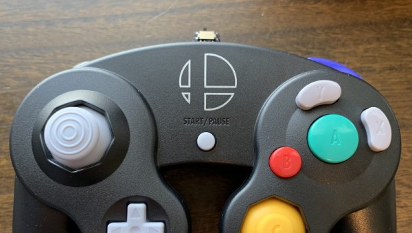
While it might not be the most traditional design, there’s no debating that Nintendo created something truly special when they unleashed the GameCube controller on an unsuspecting world back in 2001. Hardcore fans are still using the controller to this day with current-generation Nintendo consoles, and there’s considerable interest in adding modern conveniences like USB support to the nearly 20-year-old design.
One particularly promising project is the BlueCubeMod created by [Nathan Reeves]. He’s developed a small custom PCB that can be installed into an official GameCube controller to turn it into a Bluetooth device. You do have to sacrifice the original cord and force feedback for this mod, but we think many will see the ability to use this iconic controller with their computer or phone as a pretty fair trade.
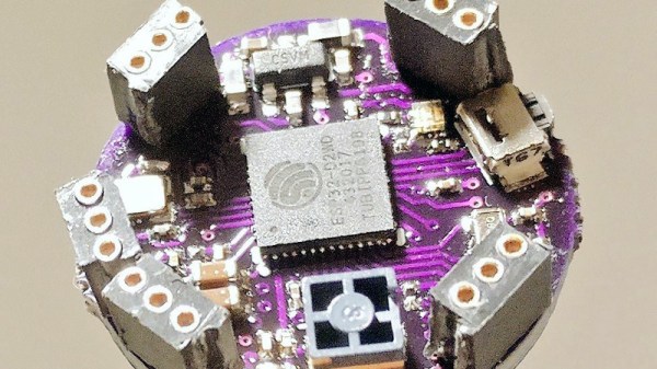
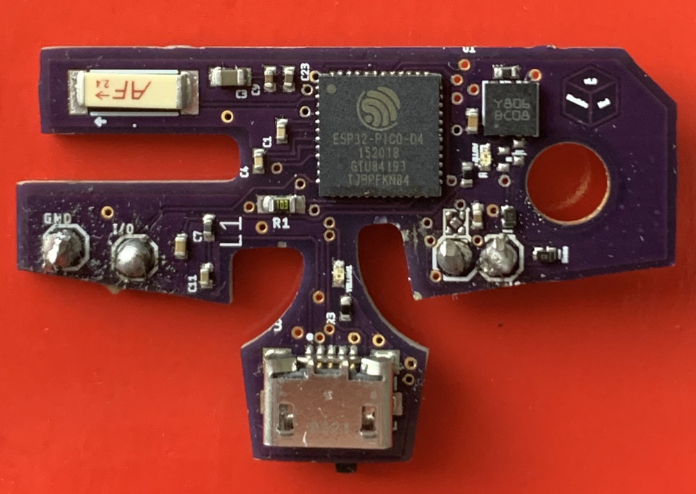 The PCB holds an ESP32-PICO-D4 which is operating as a standard Bluetooth HID controller for maximum compatibility with modern systems. Control signals are pulled directly from the controller’s original PCB with just two wires, making the installation very simple. Wondering where the power comes from? As the rumble motor isn’t supported anyway, that gets tossed and in its places goes a 700 mAh battery which powers the controller for up to six hours. Overall it’s a very clean modification that [Nathan] believes even beginners will be capable of, and he ultimately plans to turn this design into a commercial kit.
Currently you still need a receiver if you want to use the BlueCubeMod with the Nintendo Switch, but [Nathan] says he’s working on a way to get around that requirement by potentially switching out the ESP32 for a STM32 with a CC256x radio. He says this will give him more direct control over the Bluetooth communications, which should allow him to take into tackle the intricacies of talking to the Switch directly.
Of course, the GameCube did have an official wireless controller back in the day. We’ve seen modifications to get the WaveBird to get it talking to modern systems as well, but there’s something to be said for slimmer form factor of the original edition.
Continue reading “ESP32 Adds Bluetooth To GameCube Controllers”