Learning Verilog For FPGAs: The Tools And Building An Adder

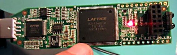
Over the last year we’ve had several posts about the Lattice Semiconductor iCEstick which is shown below. The board looks like an overgrown USB stick with no case, but it is really an FPGA development board. The specs are modest and there is a limited amount of I/O, but the price (about $22, depending on where you shop) is right. I’ve wanted to do a Verilog walk through video series for awhile, and decided this would be the right target platform. You can experiment with a real FPGA without breaking the bank.

In reality, you can learn a lot about FPGAs without ever using real hardware. As you’ll see, a lot of FPGA development occurs with simulated FPGAs that run on your PC. But if you are like me, blinking a virtual LED just isn’t as exciting as making a real one glow. However, for the first two examples I cover you don’t need any hardware beyond your computer. If you want to get ready, you can order an iCEstick and maybe it’ll arrive before Part III of this series if published.

Continue reading “Learning Verilog For FPGAs: The Tools And Building An Adder”

4-bit Adder Built From Mechanical Relays

relay-adder-register-memory

Would you consider this to be doing math the old-fashioned way? Instead of going with silicon-based switching (ie: transistors) this 4-bit adder uses mechanical relays. We like it for its mess of wires (don’t miss the “assembly” page which is arguably the juiciest part of the project). We like it for the neat and tidy finished product. And we like it for the clicky-goodness which surely must bloom from its operation; but alas, we didn’t find a video to stand as testament to this hypothesis.

The larger of the two images seen above is from the register memory stage of the build. The black relay in the bottom right is joined by a ring of siblings that are added around the perimeter of the larger relays before the entire thing is planted in the project box.

Sure, simulators are a great way to understand building blocks of logic structures like an adder. But there’s no better way to fully grip the abstraction of silicon logic than to build one from scratch. Still hovering on our list of “someday” projects is this wooden adder.

[Thanks Alex]


Mechanical CPU Clock Is Just As Confusing As Its Namesake

[Lior Elazary] designed and built this clock to simulate the function of a CPU. The problem is that if you don’t already have a good grasp of how a CPU works we think this clock will be hopelessly confusing. But lucky for us, we get it, and we love it!

Hour data is shown as a binary number on Register A. This is the center column of red parts and is organized with the MSB on the bottom, the LSB on the top, and left-pointing bits function as digital 1. The clock lacks the complexity necessary for displaying any other time data. But that’s okay, because the sound made by the ball-bearing dropping every minute might drive you a bit loony anyway. [Lior] doesn’t talk about the mechanism that transports that ball bearing, but you can see from the video after the break that a magnet on a circular path picks it up and transports it to the top of the clock where gravity is used to feed the registers. There are two tracks which allow the ball to bypass the A register and enter the B register to the right. This works in conjunction with register C (on the left) to reset the hours when the count is greater than 11.

If you need a kickstart on how these mechanical adders are put together, check out this wooden adder project.

Continue reading “Mechanical CPU Clock Is Just As Confusing As Its Namesake”

Binary Adder Will Give You Slivers

marble_adder

A while back we looked at [Matthias’] one-pin dot matrix printer. Now we’re jumping over to his woodworking website to feast on his wooden binary adding machine. His creation uses glass marbles as the data for this device. A resolution of up to six bits can be set on the top of the adder, then dropped into the machine as one number. With each new drop, the number is added to the total stored in the machine. The device is limited to totals less than 64. If a larger number is enter, the device wraps around back to zero by dumping the 7th bit off the end. He’s even got a master clear that allows you to easily read the stored total and evacuate the “data” from the machine.

This has quite a few less wires than the last binary adder we looked at… wait, it has no wires! But we still love it. A physical representation of what is going on with binary math really helps grasp what the magic blue smoke inside those silicon chips is all about. Don’t miss his video walk through of the adding machine embedded after the break. Can’t get enough of marbles interacting with wood? He’s got a few more projects you might enjoy. Continue reading “Binary Adder Will Give You Slivers”