Arrow’s $30 FPGA Board Reviewed

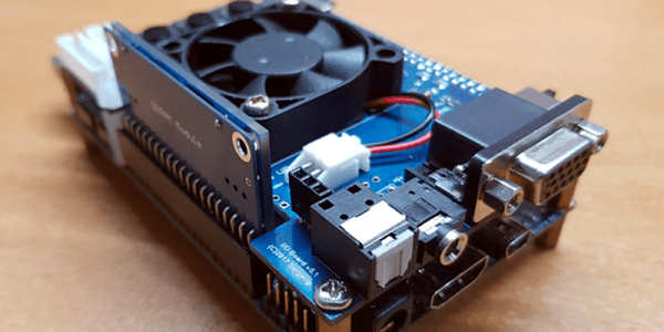
We like cheap FPGA boards. It isn’t just that we’re cheap — although that’s probably true, too — but cheap boards are a good way to get people started on FPGAs and we think more people should be using FPGAs more often. One inexpensive board is the Max-1000 from Trenz and Arrow. At $29, it is practically an impulse buy. [ZipCPU] did a great write up on his experience using the board. He found that some of it was good, some was bad, and some was just plain ugly. Still, for $30, it seems like this might be a nice board for some applications or for getting started.

Billed an IoT Maker Board, the tiny board sports a Intel (formerly Altera) MAX10 device with 8,000 logic elements, a USB programming interface onboard, 8 MB of SDRAM, and both PMOD and Arduino MKR headers. The MAX10 has an analog to digital conversion block (with an analog mux for up to nine channels) and the ability to host a 32-bit soft controller onboard, too.

Continue reading “Arrow’s $30 FPGA Board Reviewed”

MiSTer Upgrades Vintage Computer Recreations

The MiST project provides an FPGA-based platform for recreating vintage computers. We recently saw an upgraded board — MiSTer — with a similar goal but with increased capability. You can see a video of the board acting like an Apple ][ playing Pac Man, below.

The board isn’t emulating the target computer. Rather, it uses an FPGA to host a hardware implementation of the target. There are cores for Apple, Atari, Commodore, Coleco, Sega, Sinclair and many other computers. There are also many arcade game cores for games like Defender, Galaga, and Frogger.

Continue reading “MiSTer Upgrades Vintage Computer Recreations”

Build One, Get Two: CPLD And STM32 Development On A Single Board

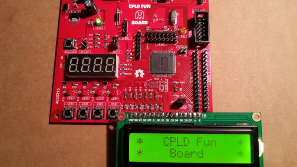
Programmable logic devices have claimed their place in the hobbyist world, with more and more projects showing up that feature either a CPLD or their bigger sibling, the FPGA. That place is rightfully earned — creating your own, custom digital circuitry not only adds flexibility, but opens up a whole new world of opportunities. However, this new realm can be overwhelming and scary at the same time. A great way to ease into this is combining the programmable logic with a general purpose MCU system that you already know and are comfortable with. [Just4Fun] did just that with the CPLD Fun Board, a development board connecting an Arduino compatible STM32F103 Cortex-M3 controller to an Altera MAX II CPLD.

The PCB itself has some standard development board equipment routed to the CPLD: LEDs, buttons, a seven-segment display, and additional GPIO. The rest of the CPLD’s pins are going straight to the STM32 and its SPI, I2C and UART pins. Let’s say you want to create your own SPI device. With the CPLD Fun Board, you can utilize all the pre-existing libraries on the STM32 and fully focus on the programmable logic part. Better yet, every connection from MCU to CPLD has its own pin header connection to attach your favorite measurement device for debugging. And in case you’re wondering — yes, you can attach external hardware to those connectors by setting either MCU or CPLD pins to Hi-Z.

The downside of all this is the need for proprietary design software and a dedicated programmer for the CPLD, which sadly is the everyday reality with programmable logic devices. [Just4Fun] did a great job though writing up a detailed step-by-step tutorial about setting up the environment and getting started with the board, but there are also other tutorials on getting started with CPLDs out there, in case you crave more.

Apple II FPGA

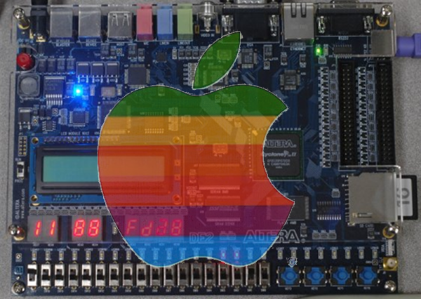
[Stephen Edwards] had some time one Christmas. So he took a DE2 FPGA board and using VHDL built a pretty faithful reproduction of an Apple II+ computer. He took advantage of VHDL modules for the 6502 CPU and PS/2 keyboard, and focused more on the video hardware and disk emulation.

According to [Stephen], you can think of the Apple II as a video display that happens to have a computer in it. The master clock is a multiple of the color burst frequency, and the timing was all geared around video generation. [Stephen’s] implementation mimics the timing, although using more modern FPGA-appropriate methods.

Continue reading “Apple II FPGA”

Mag Lev Without The Train (But With An FPGA)

It always surprises us that magnetic levitation seems to have two main purposes: trains and toys. It is reasonably inexpensive to get floating Bluetooth speakers, globes, or just floating platforms for display. The idea is reasonably simple, especially if you only care about levitation in two dimensions. You let an electromagnet pull the levitating object (which is, of course, ferrous). A sensor detects when the object is at a certain height and shuts off the magnet. The object falls, which turns the magnet back on, repeating the process. If you do it right, the object will reach equilibrium and hover near the sensor.

Some students at Cornell University decided to implement the control loop to produce levitation using an Altera FPGA. An inductive sensor determined the position of an iron ball. The device uses a standard proportional integral derivative (PID) control loop. The control loop and PWM generation occur in the FPGA hardware. You can see a video of their result, below.

Continue reading “Mag Lev Without The Train (But With An FPGA)”

No Frame Buffer For FPGA VGA Graphics

Usually, when you think of driving a VGA–in software or hardware–you think of using a frame buffer. The frame buffer is usually dual port RAM. One hardware or software process fills in the RAM and another process pulls the data out at the right rate and sends it to the VGA display (usually through a digital to analog converter).

[Connor Archard] and [Noah Levy] wanted to do some music processing with a DE2-115 FPGA board. To drive the VGA display, they took a novel approach. Instead of a frame buffer, they use the FPGA to compute each pixel’s data in real-time.

Continue reading “No Frame Buffer For FPGA VGA Graphics”

FPGA Powers Blazingly Fast LED Matrix Audio Visualizer

[Sam Miller], [Sahil Gupta], and [Mashrur Mohiuddin] worked together on a very fast LED matrix display for their final project in ECE 5760 at Cornell University.

Real time!
Real time!

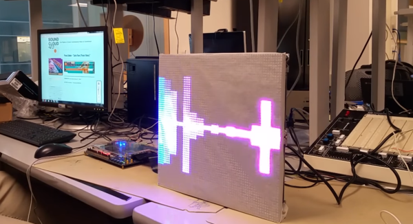
They started, as any good engineering students, by finding a way to make their lives easier. [Sam] had built a 32×32 LED matrix for another class. So, they made three more and ended up with a larger and more impressive 64×64 LED display.

They claim their motivation was the love of music, but we have a suspicion that the true reason was the love all EEs share for unnaturally bright LEDs; just look at any appliance at night and try not be blinded.

The brains of the display is an Altera DE2-115 FPGA board. The code is all pure Verilog. The FFT and LED control are implemented in hardware on the FPGA; none of that Altera core stuff. To generate images and patterns they wrote a series of python scripts. But for us it’s the particle test shown in the video below that really turns our head. This system is capable of tracking and reacting to a lot of different elements on the fly why scanning the display at about 310 FPS. They have tested display scanning at twice that speed but some screen-wrap artifacts need to be worked out before that’s ready for prime time.

The team has promised to upload all the code to GitHub, but it will likely be a while before the success hangover blows over and they can approach the project again. You can view a video interview and samples of the visualizations in the videos after the break.

Thanks to their Professor, [Bruce Land], for submitting the tip! His students are always doing cool things. You can even watch some of his excellent courses online if you like: Here’s one on the AVR micro-controller.

Continue reading “FPGA Powers Blazingly Fast LED Matrix Audio Visualizer”