How Much Bandwidth Does CW Really Occupy?

Amateur radio license exams typically have a question about the bandwidths taken up by various modulation types. The concept behind the question is pretty obvious — as guardians of the spectrum, operators really should know how much space each emission type occupies. As a result, the budding ham is left knowing that continuous wave (CW) signals take up a mere 150 Hertz of precious bandwidth.

But is that really the case? And what does the bandwidth of a CW signal even mean, anyway? To understand that, we turn to [Alan (W2AEW)] and his in-depth look at CW bandwidth. But first, one needs to see that CW signals are a bit special. To send Morse code, the transmitter is not generating a tone for the dits and dahs and modulating a carrier wave, rather, the “naked” carrier is just being turned on and off by the operator using the transmitter’s keyer. The audio tone you hear results from mixing the carrier wave with the output of a separate oscillator in the receiver to create a beat frequency in the audio range.

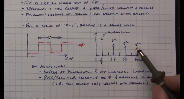
That seems to suggest that CW signals occupy zero bandwidth since no information is modulated onto the carrier. But as [Alan] explains, the action of keying the transmitter imposes a low-frequency square wave on the carrier, so the occupied bandwidth of the signal depends on how fast the operator is sending, as well as the RF rise and fall time. His demonstration starts with a signal generator modulating a 14 MHz RF signal with a simple square wave at a 50% duty cycle. By controlling the keying frequency, he mimics different code speeds from 15 to 40 words per minute, and his fancy scope measures the occupied bandwidth at each speed. He’s also able to change the rise and fall time of the square wave, which turns out to have a huge effect on bandwidth; the faster the rise-fall, the larger the bandwidth.

It’s a surprising result given the stock “150 Hertz” answer on the license exam; in fact, none of the scenarios [Allen] tested came close to that canonical figure. It’s another great example of the subtle but important details of radio that [Alan] specializes in explaining.

Continue reading “How Much Bandwidth Does CW Really Occupy?”

Open HT Surgery Gives Cheap Transceiver All-Band Capabilities

Watch out, Baofeng; there’s a new kid on the cheap handy talkie market, and judging by this hardware and firmware upgrade to the Quansheng UV-K5, the radio’s hackability is going to keep amateur radio operators busy for quite a while.

Like the ubiquitous Baofeng line of cheap transceivers, the Quansheng UV-K5 is designed to be a dual-band portable for hams to use on the 2-meter VHF and 70-centimeter UHF bands. While certainly a useful capability, these bands are usually quite range-limited, and generally require fixed repeaters to cover a decent geographic area. For long-range comms you want to be on the high-frequency (HF) bands, and you want modulations other than the FM-only offered by most of the cheap HT radios.

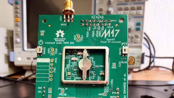
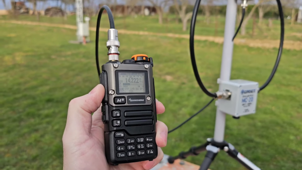
Luckily, there’s a fix for both problems, as [Paul (OM0ET)] outlines in the video below. It’s a two-step process that starts with installing a hardware kit to replace the radio’s stock receiver chip with the much more capable Si4732. The kit includes the chip mounted on a small PCB, a new RF choke, and a bunch of nearly invisible capacitors. The mods are straightforward but would certainly benefit from the help of a microscope, and perhaps a little hot air rework. Once the hardware is installed and the new firmware flashed, you have an HT that can receive signals down to the 20-meter band, with AM and SSB modulations, and a completely redesigned display with all kinds of goodies.

It’s important to note that this is a receive-only modification — you won’t be transmitting on the HF bands with this thing. However, it appears that the firmware allows you to switch back and forth between HF receive and VHF/UHF transceive, so the radio’s stock functionality is still there if you need it. But at $30 for the radio and $12 for the kit, who cares? Having a portable HF receiver could be pretty handy in some situations. This looks like yet another fun hack for this radio; we’ve seen a few recently, including a firmware-only band expansion and even a Trojan that adds a waterfall display and a game of Pong. Continue reading “Open HT Surgery Gives Cheap Transceiver All-Band Capabilities”

HF In Small Spaces

Generally, the biggest problem a new ham radio operator will come across when starting out on the high frequency (HF) bands is finding physical space for the antennas. For a quick example, a dipole antenna for the 20 m band will need around 10 m of wire, and the lower frequencies like 80 m need about four times as much linear space. But if you’re willing to trade a large space requirement for a high voltage hazard instead, a magnetic loop antenna might be just the ticket.

Loop antennas like these are typically used only for receiving, but in a pinch they can be used to transmit as well. To tune the antennas, which are much shorter than a standard vertical or dipole, a capacitor is soldered onto the ends, which electrically lengthens the antenna. [OM0ET] is using two loops of coax cable for the antenna, with each end soldered to one half of a dual variable capacitor which allows this antenna to tune from the 30 m bands to the 10 m bands, although he is using it mostly for WSPR on 20 m. His project also includes the use of an openWSPR module, meaning that he doesn’t have to dedicate an entire computer to run this mode.

The main downsides of antennas like these is that they are not omnidirectional, are not particularly good at transmitting, and develop a significantly high voltage across the capacitor as this similar mag loop antenna project demonstrated. But for those with extreme limitations on space or who, like [OM0ET] want a simple, small setup for running low-power applications like WSPR they can really excel. In fact, WSPR is a great mode for getting on the air at an absolute minimum of cost.

Continue reading “HF In Small Spaces”

A Ham Radio Answering Machine

For those who grew up with a cell phone in their hand, it might be difficult to imagine a time where the phone wasn’t fully integrated with voicemail. It sounds like a fantastical past, yet at one point a separate machine needed to be attached to the phone to record messages if no one was home to answer. Not only that, but a third device, a cassette tape, was generally needed as a storage device to hold the messages. In many ways we live in a much simpler world now, but in the amateur radio world one group is looking to bring this esoteric technology to the airwaves and [saveitforparts] is demonstrating one as part of a beta test.

The device is called the Boondock Echo, and while at its core it’s an ESP32 there’s a lot going on behind the scenes. It has an audio interface which is capable of connecting to a radio given the correct patch cable; in this case with a simple Baofeng handheld unit. The answering machine can record any sounds that come in. However, with a network connection the recordings are analyzed with an AI which can transcribe what it hears and even listen for specific call signs, then take actions such as sending emails when it hears triggers like that. Boondock also plans for this device to be capable of responding as well, but [saveitforparts] was not able to get this working during this beta test.

While an answering machine might seem like a step backwards technologically, an answering machine like this, especially when paired with Google Voice-like capabilities from an AI, has a lot of promise for ham radio operators. Even during this test, [saveitforparts] lost a radio and a kind stranger keyed it up when it was found, which was recorded by the Boondock Echo and used to eventually recover the radio. Certainly there are plenty of other applications as well, such as using AI instead of something like an Arduino to do Morse decoding.

Continue reading “A Ham Radio Answering Machine”

Pico-WSPR-tx Does It In Software

What do you need to make a radio transmitter? There are builds that work with just a couple of transistors. But how about a GPS-disciplined small signal beacon? You can actually get the job done for less than the cost of a fancy hamburger, thanks to [RPiks]’s pico-WSPR-tx and the Weak Signal Propagation Reporter Network (WSPR).

WSPR is a digital protocol where a beacon encodes its callsign, location, and transmitting power, and then sends it out to a network of receiving stations worldwide. The idea is to use the data coming from the beacons to determine whether radio propagation conditions are good or not; if you hear a quiet signal from afar, they’re good in that direction. [RPiks]’s beacon design simply includes a Raspberry Pi Pico and a GPS receiver. Everything else is software.

Of course, this means that it’s using the Pico’s GPIO pins for transmission. Maybe you want to add some filtering to take off the rough square-wave edges, and/or maybe you want to boost the power a little bit with an external amplifier. If so, check out our own $50 Ham column’s advice on the topic. But you don’t need to. Just a Pico and a GPS should get you working, if you want to test the WSPR waters.

DIY Loading Coil Shortens Antenna Lengths

A newly licensed amateur radio operator’s first foray into radios is likely to be a VHF or UHF radio with a manageable antenna designed for the high frequencies in these radio bands. But these radios aren’t meant for communicating more than a double-digit number of kilometers or miles. The radios meant for long-distance communication use antennas that are anything but manageable, as dipole antennas for the lowest commonly used frequencies can often be on the order of 50 meters in length. There are some tricks to getting antenna size down like folding the dipole in all manner of ways, but the real cheat code for reducing antenna size is to build a loading coil instead.

As [VA5MUD] demonstrates, a loading coil is simply an inductor that is placed somewhere along the length of the antenna which makes a shorter antenna behave as a longer antenna. In general, though, the inductor needs to be robust enough to handle the power outputs from the radio. There are plenty of commercial offerings but since an inductor is not much more than a coil of wire, it’s entirely within the realm of possibility to build them on your own. [VA5MUD]’s design uses a piece of PVC with some plastic spacers to wind some thick wire around, and then a customized end cap with screw terminals attached to affix the antenna and feedline to. Of course you’ll need to do a bit of math to figure out exactly how many turns of wire will be best for your specific situation, but beyond that it’s fairly straightforward.

It’s worth noting that the coil doesn’t have to be attached between the feedline and the antenna. It can be placed anywhere along the antenna, with the best performance typically being at the end of the antenna. Of course this is often impractical, so a center-loaded coil is generally used as a compromise. Coils like these are not too hard to wind by hand, but for smaller, lower-current projects it might be good to pick up a machine to help wind the coils instead.

Continue reading “DIY Loading Coil Shortens Antenna Lengths”

A Canned Ham Ham Antenna

If you’d have asked us for odds on whether you could successfully turn a canned ham into an amateur radio antenna, we’d have declined the offer. Now, having seen [Ben Eadie (VE6SFX)]’s “hamtenna” project, we’d look at just about any “Will it antenna?” project with a lot less skepticism than before.

To be painfully and somewhat unnecessarily clear about [Ben]’s antenna, the meat-like product itself is not in the BOM for this build, although he did use it as sustenance. Rather, it was the emptied and cleaned metal can that was the chief component of the build, along with a few 3D printed standoffs and the usual feedline and connectors. This is a slot antenna, a design [Ben] recently experimented with by applying copper foil tape to his car’s sunroof. This time around, the slot was formed by separating the top and bottom of the can using the standoffs and electrically connecting them with a strip of copper tape.

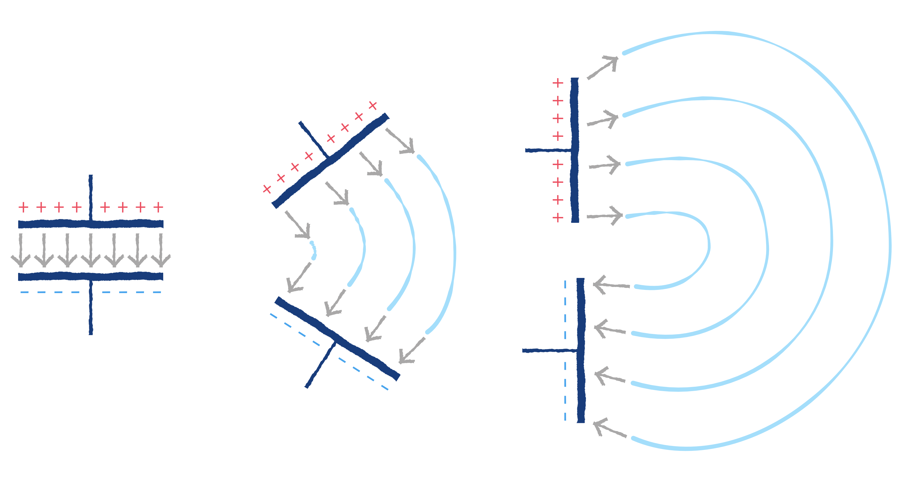
Connected to a stub of coax and a BNC connector, a quick scan with a NanoVNA showed a fantastic 1.26:1 SWR in the center of the 70-cm ham band, and a nearly flat response all the way across the band. Results may vary depending on the size of canned ham you sacrifice for this project; [Ben]’s can measured just about 35 cm around, a happy half-wavelength coincidence. And it actually worked in field tests — he was able to hit a local repeater and got good signal reports. All that and a sandwich? Not too shabby.

Continue reading “A Canned Ham Ham Antenna”