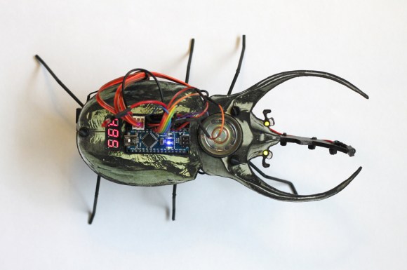
Laser Piano Worthy Of The Band ‘Wyld Stallyns’

Laser Piano uses Arduino

[Robi] and [Kathy] from elecfreaks have put together a how-to article about a Laser Piano they just built. Instead of keys, the user breaks beams of laser light to trigger the sounds.

Several laser pointer diodes are wired in parallel and mounted in a box, cardboard in this case. The laser diodes are aimed at photocells that reside on the other side of the box. Each photocellis connected to a digital input pin on an Arduino. When the Arduino senses a state change from one of the photocell, meaning the beam of light has been interrupted, it plays the appropriate wave file stored on an external JQ6500 sound module.

[Robi] admits that there are some improvements to be made, specifically the trigger response time and the piano sounding too monotonous. If you have any ideas, please leave them in the comments section.

Continue reading “Laser Piano Worthy Of The Band ‘Wyld Stallyns’”

Pew Pew! An Arduino Based Laser Rangefinder

Arduino Laser Rangefinder
Lasers are some of the coolest devices around. We can use them to cut things, create laser light shows, and also as a rangefinder.[Ignas] wrote in to tell us about [Berryjam’s] AMAZING write-up on creating an Arduino based laser rangefinder. This post is definitely worth reading.

Inspired by a Arduino based LIDAR system, [Berryjam] decided that he wanted to successfully use an affordable Open Source Laser RangeFinder (OSLRF-01) from LightWare. The article starts off by going over the basics of how to measure distance with a laser based system. You measure the time between an outgoing laser pulse and the reflected return pulse; this time directly relates to the distance of the object. Sounds simple? In practice, it is not as simple as it may seem. [Berryjam] has done a great job doing some real world testing of this device, with nice plots to top it all off. After fiddling with the threshold and some other aspects of the code, the resulting accuracy is quite good.

Recently, we have seen more projects utilizing lasers for range-finding, including LIDAR projects. It is very exciting to see such high-end sensors making their way into the maker/hacker realm. If you have a related laser project, be sure to let us know!

Build A Bass Master 3000 Carnival Game

Bass Master 3000

We’ve all been there. You are having fun walking around the carnival when you suddenly find yourself walking past the carnival games. The people working the booths are taunting you, trying to get you to play their games. You know the truth, though. Those games are rigged. You don’t know how they do it. You just know that they do… somehow.

Now you can put your worries to rest and build your own carnival game! [John] built his own “Bass Master 3000” style carnival game and posted an Instructable so you can make one too.

The game is pretty straightforward. You have a giant fish-shaped target with a wide open mouth. You take hold of a small fishing reel with a rubber ball on the end. Your goal is to cast the ball out and hit the fish in its big mouth. If you hit the mouth, you get to hear a loud buzzer and see some flashing lights. The system also uses a webcam to take a candid photo of the winner. A computer screen shows all of the winners of the day.

The brain of the system is an Arduino Yún. The Yún is similar to an Uno but it also has some extra features. Some good examples are an Ethernet port, a wireless adapter, and an SD card slot. The mouth sensors are just two piezo elements. Each sensor is hooked up to the Arduino through a small trim pot. This allows you to dial in the sensitivity of each sensor. The lights and the buzzer are controlled via a relay, triggered by a 5V digital pin on the Arduino.

The Yún actually has a small on-board Linux computer that you can communicate with from inside the Arduino environment. This allows [John] to use the Yún to actually take photos directly from a web cam, store them on the local SD card, and display them on a local web server. The web server runs a simple script that displays a slide show of all of the photos stored on the card.

The final piece of the game is the physical target itself. The target is painted using acrylic paint onto a small tarp. The tarp is then attached to a square frame made from PVC pipe. The mouth of the fish is cut out of the tarp. A large piece of felt is then placed behind the hole with the piezo sensors attached. A short length of copper pipe helps to weigh down the bottom of the felt and keep it in place. The important thing is to make sure the felt isn’t touching the tarp. If it touches, it might be overly sensitive and trigger even when a player misses.

Now you know how to build your own Bass Master 3000 carnival game. Whether you rig the game or not is up to you. Also, be sure to check out a video of the system working below. Continue reading “Build A Bass Master 3000 Carnival Game”

A SI5351 clock generator chip and an Arduino

Generate Clocks With The SI5351 And An Arduino

If you’re dealing with RF, you’ll probably have the need to generate a variety of clock signals. Fortunately, [Jason] has applied his knowledge to build a SI5351 library for the Arduino and a breakout board for the chip.

The SI5351 is a programmable clock generator. It can output up to eight unique frequencies at 8 kHz to 133 MHz. This makes it a handy tool for building up RF projects. [Jason]’s breakout board provides 3 isolated clock outputs on SMA connectors. A header connects to an Arduino, which provides power and control over I2C.

If you’re looking for an application, [Jason]’s prototype single-sideband radio shows the chip in action. This radio uses two of the SI5351 clocks: one for the VFO and one for the BFO. This reduces the part count, and could make this design quite cheap.

The Arduino library is available on Github, and you can order a SI5351 breakout board from OSHPark.

The 200 LED Ring Clock

There are LED clocks, and then there are LED clocks that can blind you from 30 paces. [Stiggalicious’s] LED ring clock is of the latter variety. 200 WS2812B/Neopixel RGB LEDs drive the ring clock to pupil searing levels. The clock runs on ATMega1284P, with timekeeping handled by an NXP PCF8563 real-time clock chip. Code is written in Arduino’s wiring language using Adafruit’s Neopixel library.

Building the clock with a single Printed Circuit Board (PCB) would be both expensive and wasteful. [Stiggalicious] cleverly designed his clock to be built with 8 copies of the same PCB. Each board makes up a 45° pie slice of the ring. All 8 PCBs have footprints for the CPU, clock chip, and other various discrete parts, but only the “master” section has these parts populated. 7 “slave” sections simply pass clock, data, power and ground through each LED. He used Seeedstudio’s board service to get 10 copies of his PCB made, just in case there were any mistakes.

[Stiggalicious] rolled the dice by buying exactly the 200 LEDs he needed. Either he got really lucky, or the WS2812 quality testing has improved, because only one LED had a dead blue LED.

If you’d like to find out more, [Stiggalicious] gives plenty of details in his Reddit thread. He doesn’t have a webpage setup for the clock but he’s uploaded his source code (pastebin link) and Altium schematic/PCB files (mega.nz link). We may be a bit biased, but hackaday.io would be a perfect spot for this or any other project!

Handheld Game System Powered By Arduino

DIY Handheld Game System

These days, it’s easy enough to play games on the go. If you have a smart phone, you are pretty much set. That doesn’t mean you can’t still have fun designing and building your own portable gaming system, though.

[randrews] did just that. He started out by purchasing a small memory LCD display from Adafruit. The screen he chose is low power as far as screens go, so it would be a good fit for this project. After testing the screen with a quick demo program, it was time to start designing the circuit board.

[randrews] used Eagle to design the circuit. He hand routed all of the traces to avoid any weird issues that the auto router can sometimes cause. He made an efficient use of the space on the board by mounting the screen over top of the ATMega chip and the other supporting components. The screen is designed to plug in and out of the socket, this way it can be removed to get to the chip. [randrews] needs to be able to reach the chip in order to reprogram it for different games.

Once the board design was finished, [randrews] used his Shapeoko CNC mill to cut it out of a copper clad board. He warns that you need to be careful doing this, since breathing fiberglass dust is detrimental to living a long and healthy life. Once the board was milled out, [randrews] used a small Dremel drill press to drill all of the holes.

The final piece of the puzzle was to figure out the power situation. [randrews] designed a second smaller PCB for this. The power board holds two 3V coin cell batteries. The Arduino expects 5V, so [randrews] had to use a voltage regulator. This power board also contains the power switch for the whole system.

The power board was milled and populated. Then it was time to do some measurements. [randrews] measured the current draw and calculates that he should be able to get around 15 hours of play time using the two 3V coin cell batteries. Not bad considering the size.

[via Reddit]

Infrared Controlled Remote Firework Igniter

Firework Igniter

With Independence Day just around the corner, American hackers are likely to find themselves blowing things up in the name of Independence. It’s all great fun but it can also be dangerous. The standard ignition method of “use a lighter and run away really fast” is not exactly safe. Instead of lighting your fireworks the old-fashioned way, why not follow [Facelesstech’s] example and build your own infrared controlled remote igniter?

The first step was to decide how to actually ignite the firework fuse. [Facelesstech] had seen others use a car cigarette lighter for this purpose and he decided to follow in their footsteps. He started by removing the cigarette lighter from his own car and pulling it apart. Only one component was needed for this hack. The main heating element is a small disk with a “stem” on the end. If you apply 12V to the stem and attach the outer edge of the disk to ground, the igniter will quickly become hot.

[Facelesstech] originally thought he could just solder some wires to the device. However, the heating element gets so hot that the solder just melts every time it’s turned on. He then got creative and drilled a hole in a small block of wood that fits the heating element. The element is bolted into the wood and the bolt is used as a conductor for the electrical power.

The heating element is powered via a 12V relay. The relay is controlled by an Arduino Nano. The Nano allows two modes of operation. With the first mode, you simply press a button and the Nano will start a five second timer. The idea is to give you enough time to run to a safe distance before the firework is ignited. This isn’t much different from the old-fashioned method, but it does give you a slightly extended fuse. The second mode is where the project really shines. The Nano is also hooked up to an infrared receiver. This allows [Facelesstech] to press a button on an old television infrared remote control to active the igniter. This is a clever solution because it allows you to get to a safe distance without having to run a long wire. It’s also simple and inexpensive. Be sure to watch the video test of the system below. Continue reading “Infrared Controlled Remote Firework Igniter”