A Deep Dive Into E-Ink Tag Hacking

Over the last decade or so, e-ink price tags have become more and more ubiquitous, and they’ve now reached the point where surplus devices can be found inexpensively on various websites. [Dmitry Grinberg] found a few of these at bargain-basement prices and decided to reverse engineer and hack them into monochrome digital picture frames.

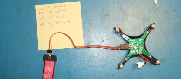
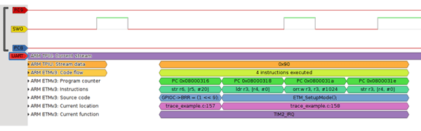
Often, the most difficult thing about repurposing surplus hardware is the potential lack of documentation. In the two tags [Dmitry] hacked, not only are the labels not documented at all, one even has an almost-undocumented SoC controlling it. After some poking around and some guesswork, he was able to find connections for both a UART and an SWD debugging interface. Fortunately, the manufacturers left the firmware unprotected, so dumping it was trivial.

Even with the firmware dumped, code for controlling peripherals (especially wireless devices) is often inscrutable. [Dmitry] overcomes this with a technique he calls “Librarification” in which he turns the manufacturer’s firmware into libraries for his custom code. Once he was able to implement his custom firmware, [Dmitry] developed his own code to wirelessly download and display both gray-scale and two-color images.

Even if you’re not interested in hacking e-ink tags, this is an incredible walk-through of how to approach reverse-engineering an embedded or IoT device. By hacking two different tags with completely different designs, [Dmitry] shows how to get into these systems with intuition, guesswork, and some sheer persistence.

If you’d like to see some more of [Dmitry]’s excellent reverse-engineering work, take a look at his reverse-engineering and ROM dump of the PokeWalker. If you’re interested in seeing what else e-ink tags can be made to do, take a look at this weather station made from the same 7.4″ e-ink tag.

ARM Programming With Bare C

We confess. When starting a microcontroller project, we often start with the last one we did for that environment, copy it, and just make changes. And the first one? It — ahem — might have been found on the Internet. There’s a lot more than just your code that goes into this. If you want  to do (and understand) absolutely everything yourself on an ARM development project, you could use an all-in-one walkthrough. It just so happens [Jacob Mossberg] has a from scratch guide of what you need to do to get your C code running on ARM.

Starting with an ARM Cortex M3, he writes a simple C program and gets the assembly language equivalent. What follows is a detailed analysis of the machine code, exploring what the compiler assumed would be set up. This leads to understanding of what the start up code and linker script needs to look like.

It is a great approach and reminded us of the old saying about “teach someone how to fish.” He even devotes a little time to talking about getting debugging working with OCD. Of course, the exact details are specific to the chip he’s using, but most of it would apply to any ARM chip. Even if you don’t use ARM, though, the thought process and methodology is itself quite interesting.

This post would be just the thing if you are using Blue Pills and ready to move away from the Arduino ecosystem. Of course, if you want to veer away from the Arduino system, but don’t want to go all the way to bare metal, there’s always mBed.

An Improved WiFi Connected E-Ink Display

[David] created a great looking e-ink WiFi display project that works a little like a network-connected picture frame with a few improvements over other similar projects. With the help of an ESP8266 it boots up, grabs an 800×600 image over the network, updates the screen, then goes back to sleep. Thanks to some reverse engineering, he was able to make his own firmware for the onboard controller to handle the low-level driving of the display. Since e-ink displays require no power to hold an image and the rest of the unit spends most of the time either asleep or off, power use is extremely low. [David] hopes to go months without needing to recharge the internal lithium-polymer battery.

eink_back
Lithium-polymer charger (top left); Single-cell lithium-polymer battery (center); pullups and power cutoff for nonessential electronics (green board, lower right); ESP866 (lower left).

We previously featured another WiFi-connected e-ink display project that was in fact also the inspiration for this version. [David] uses a 4.3″ 800×600 GDE043A e-ink display and wrote his own firmware for the STM32F103ZE ARM CortexM3 SoC used as a display controller, a process that required some reverse engineering but was aided by the manufacturer providing a closed-source driver for him to use. [David] writes that some reverse-engineering work for this display had already been done, but he had such a hard time getting a clear understanding from it that he reverse engineered the firmware anyway and used the documents mainly for validation and guidance.

As a result, [David] was able to make use of the low-level driver electronics already present on the board instead of having to make and interface his own. E-ink displays have some unusual driving requirements which include generating relatively high positive and negative voltages, and rapidly switching them when updating the display. Taking advantage of the board’s existing low-level driver electronics was a big benefit.

eink_apThe ESP8266 rounds out the project by taking care of periodically booting things up, connecting to the wireless network and downloading an image, feeding the image data to the STM32 to update the display, then disconnecting power from all non-essential electronics and going back to sleep. We especially like how the unit automatically creates a WiFi access point to allow easy (re)configuring.

There’s one more nice touch. [David] goes the extra mile with server software (in the form of PHP scripts) to design screens for the display with data like weather forecasts, stock prices, and exchange rates. Check it out in the project’s github repository.

Pacman Proves Due Is More Than Uno

If you’re wondering what the difference is between the good ol’ Arduino Uno and one of the new-school Arduinos like the Arduino Due, here’s a very graphic example: [DrNCX] has written a stunning Pacman clone for the Due that seems to play just like the arcade. (Video embedded below the break.)

001The comparison between the Uno and Due isn’t quite fair. The Due runs on an 84 MHz, 32 bit ARM Cortex-M3 processor. It’s in a different league from the Uno. Still, we view this as an example of the extended possibilities from stepping up into a significantly faster micro. For instance, the video is output to both an ILI9341 TFT screen and external 8-bit VGA at once.

Besides using some very nice (standard) libraries for the parts, it doesn’t look like [DrNCX] had to resort to any particular trickery — just a lot of gamer-logic coding. All the code is up on GitHub for you to check out.

Can the old Arduinos do this? For comparison, the best Pacman we’ve seen on an AVR platform is the ATmega328-based RetroWiz, although it is clocked twice as fast as a stock Uno. And then there’s Hackaday Editor [Mike Szczys]’s 1-Pixel Pacman, but that’s cheating because it uses a Teensy 3.1, which is another fast ARM chip. People always ask where the boundary between an 8-bit and 32-bit project lies. Is a decent Pacman the litmus test?

Continue reading “Pacman Proves Due Is More Than Uno”

Open-Source Firmware For A Mini Quadrotor

Since you’re going to have to be flying your “drones” indoors anyway in the USA, at least in the US Capitol region, you might as well celebrate the one freedom you still have — the freedom to re-flash the firmware!

The Eachine H8 is a typical-looking mini-quadcopter of the kind that sell for under $20. Inside, the whole show is powered by an ARM Cortex-M3 processor, with the programming pins easily visible. Who could resist? [garagedrone] takes you through a step-by-step guide to re-flashing the device with a custom firmware to enable acrobatics, or simply to tweak the throttle-to-engine-speed mapping for the quad. We had no idea folks were doing this.

Spoiler alert: re-flashing the firmware is trivial. Hook up an ARM SWD programmer (like the ST-Link V2) and you’re done. Wow. All you need is firmware.

The firmware comes from [silverxxx], and he’s written all about it on the forum at RCGroups.com. He’s even got the code up on GitHub if you’re interested in taking a peek. It looks like it’d be fun to start playing around with the control algorithms. Next step, Skynet!

Reading the forum post, it looks like you’ll have to be a little careful to get the right model quad, so look before you leap. But for the price, you can also afford to mess up once. Heck, at that price you could throw away the motors and you’d have a tricked-out ARM dev kit.

And if you insist on hacking everything, you can probably re-purpose a wireless mouse controller to control the thing. Write your own code for the controller and you’ve got an end-to-end open firmware quadcopter for a pittance.

Execution Tracing On Cortex-M3 Microcontrollers

The higher-power ARM micros have a bunch of debugging tools for program and data tracing, as you would expect. This feature – CoreSight Trace Macrocells – is also found in the lowly ARM Cortex M3 microcontroller. The Cortex M3 is finding its way into a lot of projects, and [Petteri] wondered why these debugging tools weren’t seen often enough. Was it a question of a lack of tools, or a lack of documentation? It doesn’t really matter now, as he figured out how to do it with a cheap logic analyzer and some decoders for the trace signals.

There are two trace blocks in most of the Cortex M3 chips: the ITM and ETM. The Instrumentation Trace Macrocell is the higher level of the two, tracing watchpoints, and interrupts. The Embedded Trace Macrocell shows every single instruction executed in the CPU.  Both of these can be read with a cheap FX2-based logic analyzer that can be found through the usual outlets for about $10. The problem then becomes software, for which [Petteri] wrote a few decoders.

To demonstrate the debugging capability, [Petteri] tracked down a bug in his CNC controller of choice, the Smoothieboard. Every once in a great while, the machine would miss a step. With the help of the trace tool and by underclocking the micro, [Petteri] found the bug in the form of a rounding error of the extruder. Now that he knows what the bug is, he can figure out a way to fix it. He hasn’t figured that out yet. Still, knowing what to fix is invaluable and something that couldn’t be found with the normal set of tools.

TiLDA MKe: The EMF 2014 Badge

The TiLDA badge from EMF 2014


Hardware conference badges keep getting more complex, adding features that are sometimes useful, and sometimes just cool. The Electromagnetic Field (EMF) 2014 badge, TiLDA MKe, is no exception.

This badge displays the conference schedule, which can be updated over an RF link with base stations. It even notifies you when an event you’re interested in is about to start. Since we’ve missed many a talk by losing track of the time, this seems like a very useful feature.

Beyond the schedule, the device has a dedicated torch button to turn it into a flashlight. A rather helpful feature seeing as EMF takes place outdoors, in a field of the non-electromagnetic sort. They’re also working on porting some classic games to the system.

The badge is compatible with the Arduino Due, and is powered by an ARM Cortex M3. It’s rechargeable over USB, which is a nice change from AA powered badges. It also touts a radio transceiver, joystick, accelerometer, gyroscope, speaker, infrared, and is compatible with Arduino shields.

For more technical details, you can check out the EMF wiki. EMF 2014 takes place from August 29th to the 31st in Bletchley, UK, and you can still purchase tickets to score one of these badges.