7 LED’s, 2 Pins – Beat That, Charlieplexing

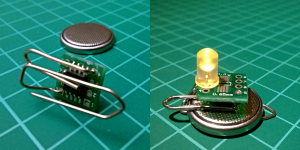
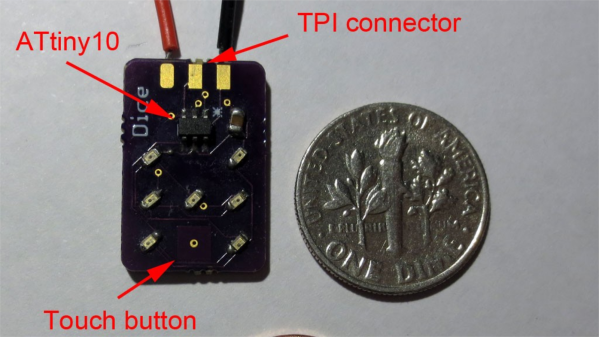
[Tim]’s Dice10 is an exercise in minimalism. Building an electronic dice using an ATtiny10 with code that fits within 1kB is not too difficult. Charlieplexing the LED’s would have used three of the four available GPIO pins. [Tim] upped the game by using just two GPIO pins to drive the seven LED’s for the dice. A third GPIO is used as a touch button input. Besides the ATtiny and the LED’s, the only other component used is a capacitor across the supply inputs.

2 GPIO for 7 LED's
2 GPIO for 7 LED’s

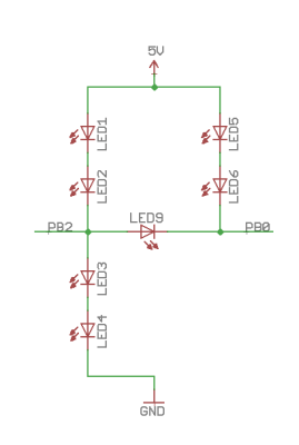
The LED’s are grouped in three pairs of two LED’s and a single centre LED. Usually, Charlieplexed LED’s are connected across pairs of GPIO pins. But his scheme includes connections to the 5V and GND terminals, besides the two GPIO pins. Building a truth table makes it easy to figure out what’s going on.

STATE PB2 PB0 LED's
1     Z   Z   --
2     L   Z   LED 1/2
3     H   Z   LED 3/4
4     Z   L   LED 5/6
5     Z   H   --
6     H   L   LED9
7     L   H   --
8     H   H   --
9     L   L   --

Only the logic states used are listed in the table. It’s possible to add two more LED’s between PB0 and GND and one more anti-parallel with LED9, making a total of 10 LED’s driven by two pins. That’s quite a hack. The important thing here is to have two LED’s in series in the arms that connect to either 5V or GND.

[Tim] has posted  the code and hardware source files on his Github repo, and his blog post has some additional details on how he solved the problem.

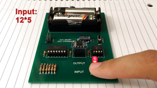
If you’re looking for more inspirations on minimal dice designs, check this “PIC powered pair of electronic dice” which uses a PIC 12F629 with five outputs driving a pair of 7 pips to make a dual dice.

1kb-thumb

If you have a cool project in mind, there is still plenty of time to enter the 1 kB Challenge! Deadline is January 5, so check it out and fire up your assemblers!

Minimal Computer And Operating System: One Button, One LED

DUO BINARY is a very, very small computer system in every possible sense. It runs on an ATtiny84, which has even got “tiny” in its name. The user interface is a single button for data entry and a single LED for feedback, making this binary keyboard look frivolously over-complicated. It uses a devilish chimera of Morse code and a truncated ASCII to enter data, and the LED blinks the same back at you.

We’re guessing that [Jack Eisenmann] is the only person in the world who can control this thing, and you can watch him doing so in the video embedded below. Continue reading “Minimal Computer And Operating System: One Button, One LED”

A Real Turn Off

[Newbrain] had a small problem. He’d turn off the TV, but would leave the sound system turned on. Admittedly, not a big problem, but an annoyance, none the less. He realized the TV had a USB port that went off when it did, so he decided to build something that would sense when the USB port died and fake a button press into the amplifier.

He posted a few ideas online and, honestly, the discussion was at least as interesting as the final project. The common thread was to use an optoisolator to sense the 5 V from the USB port. After that, everyone considered a variety of ICs and discretes and even did some Spice modeling.

In the end, though, [Newbrain] took the easy way out. An ATtiny 84 is probably overkill, but it easy enough to press into service. With only three other components, he built the whole thing into a narrow 24-pin socket and taped it to the back of the audio unit’s wired remote control.

Continue reading “A Real Turn Off”

Raspberry Pi Plays All That Jazz

[James Bellafaire] wanted a good looking old radio with a modern sound. Granted, you could hollow the case out and replace it with an iPod. Or you could convert the thing to an Internet radio. But where’s the fun in that?

[James] took a different approach. Part woodworking project, part Raspberry Pi project, and part microcontroller project, he wound up with a hard drive-based music player in a 1930’s case with knobs that control the playback.

Continue reading “Raspberry Pi Plays All That Jazz”

How I²C EEPROM Talks To The Bus

You will probably be familiar with I²C, a serial bus typically used for not-very-fast communication with microcontroller peripherals. It’s likely though that unless you are an I²C wizard you won’t be intimately familiar with the intricacies of its operation, and each new device will bring a lengthy spell of studying data sheets and head-scratching.

If the previous paragraph describes you, read on. [Clint Stevenson] wrote a library for interfacing I²C EEPROMs to Arduino platforms, and when a user found a bug when using it on an ATtiny85, he wrote up his solution. The resulting piece is a clear explanation of how I²C EEPROMs talk to the bus, the various operations you can perform on them, and the overhead each places on the bus. He then goes on to explain EEPROM timing, and how since it takes the device a while to perform each task, the microcontroller must be sure it has completed before moving to the next one.

In the case of [Clint]’s library, the problem turned out to be a minor incompatibility with the Arduino Wire library over handling I²C start conditions. I²C has a clock and a data line, both of which are high when no tasks are being performed. A start condition indicates to the devices on the bus that something is about to happen, and is indicated by the data line going low while the clock line stays high for a while before the clock line starts up and the data line carries the I²C command. He’s posted samples of code on the page linked above, and you can find his library in his GitHub repository.

If you want to know more about I²C, take a look at Hackaday Editor [Elliot Williams’] masterclasses on the subject: What could go wrong, I²C edition, and Embed With Elliot, I²C bus scanning.

Serial EEPROM die picture, By Epop (Own work) [CC0], via Wikimedia Commons.

The Quest For Mice With Frickin’ Laser Beams (Pointed At Their Brains), Building A Laser Controller

The logo for the field is kind of cute though.

[Scott Harden] is working on a research project involving optogenetics. From what we were able to piece together optogenetics is like this: someone genetically modifies a mouse to have cell behaviors which can activated by light sensitive proteins. The mice then have a frikin’ lasers mounted on their heads, but pointing inwards towards their brains not out towards Mr. Bond’s.

Naturally, to make any guesses about the resulting output behavior from the mouse the input light has to be very controlled and exact. [Scott] had a laser and he had a driver, but he didn’t have a controller to fire the pulses. To make things more difficult, the research was already underway and the controller had to be built

The expensive laser driver had a bizarre output of maybe positive 28 volts or, perhaps, negative 28 volts… at eight amps. It was an industry standard in a very small industry. He didn’t have a really good way to measure or verify this without either destroying his measuring equipment or the laser driver. So he decided to just build a voltage-agnostic input on his controller. As a bonus the opto-isolated input would protect the expensive controller.

The kind of travesty that can occur when [Stefan Kiese] doesn't have access to nice project boxes.
The kind of travesty that can occur when [Scott] doesn’t have access to nice project boxes.
The output is handled by an ATtiny85. He admits that a 555 circuit could generate the signal he needed, but to get a precision pulse it was easier to just hook up a microcontroller to a crystal and know that it’s 100% correct. Otherwise he’d have to spend all day with an oscilloscope fiddling with potentiometers. Only a few Hackaday readers relish the thought as a relaxing Sunday afternoon.

He packaged everything in a nice project box. He keeps them on hand to prevent him from building circuits on whatever he can find. Adding some tricks from the ham-radio hobby made the box look very professional. He was pleased and surprised to find that the box worked on his first try.

AVR Vs PIC, Round 223: Fight!

Get ready to rumble! [Thierry] made the exact same Hello-World-esque project with two microcontrollers (that are now technically produced by the same firm!) to see how the experience went.

It’s not just an LED-blinker, though. He added in a light-detection function so that it only switches on at night. It uses the Forest Mims trick of reverse-biasing the LED and waiting for it to discharge its internal capacitance. The point is, however, that it gives the chip something to do instead of simply sleeping.

Although he’s an AVR user by habit, [Thierry] finds in favor of the PIC because it’s got a lower power draw both when idling and when awake and doing some computation. This is largely because the PIC has an onboard low-power oscillator that lets it limp along at 32 kHz, but also because the chip has a lower power consumption in general. In the end, it’s probably a 10% advantage to the PIC on power.

If you’re competent with one of the two chips, but not the other, his two versions of the same code would be a great way to start familiarizing yourself with the other. We really like his isDarkerThan() function which makes extensive use of sleep modes on both chips during the LED’s discharge period. And honestly, at this level the code for the two is more similar than different.

(Oh, and did you notice [Thierry]’s use of a paper clip as a coin-cell holder? It’s a hack!)

Surprisingly, we’ve managed to avoid taking a stray bullet from the crossfire that occasionally breaks out between the PIC and AVR fans. We have covered a “shootout” before, and PIC won that round too, although it was similarly close. Will the Microchip purchase of Atmel calm the flames? Let’s find out in the comment section. We have our popcorn ready!