Hackaday Superconference: Pushing The Boundaries Of PCB Artwork With Brian Benchoff

The artistic elite exists in a stratum above we hoi polloi, a world of achingly trendy galleries, well-heeled collectors, and art critics who act as gatekeepers to what is considered the pinnacle du jour of culture. Artistic movements that evolve outside this bubble may be derided or ignored as naive and unsophisticated, even in complete denial of their raw creative edge. When they are discovered by the establishment a few of their artists are selected and anointed, while inevitably the crucible in which they were formed is forgotten. On the streets of Bristol the incredible work of far more graffiti artists can be seen than just that of Banksy.

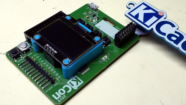
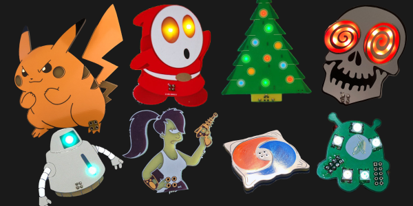
Our community has an art form all of its own, in the guise of PCB artwork and the #BadgeLife community. One day you will see electronic badges from darlings of the art world behind glass in those trendy galleries, but for now they live in glorious abundance in the wild. Here at Hackaday we are lucky enough to have in Brian Benchoff a colleague who is pushing the boundaries of PCB art, and at the Hackaday Superconference he took us through one of his more recent pieces of work.

Brian's pad printer.
Brian’s pad printer.

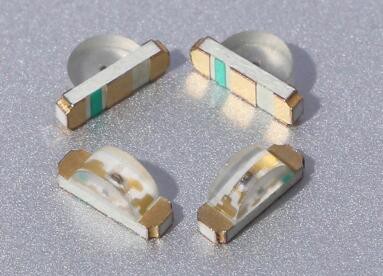
The colour palette of a typical printed circuit board is limited by the combination of fibreglass, copper, soldermask, plating, and silkscreen its designer selects. Thus while the variety of soldermask colours and plating materials can make for an eye-catching work, they have remained a colour-tinted near monochrome. The Holy Grail of the PCB artist has been to step into the world of full colour, and Brian has been pursuing that goal by exploring pad printing to produce extra colours beyond the sodermask..

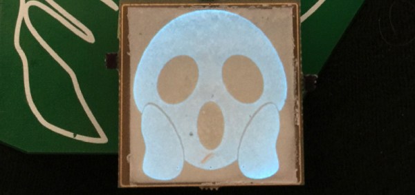
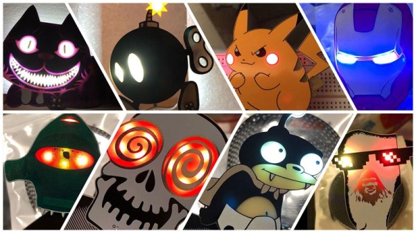
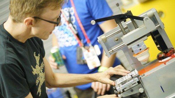
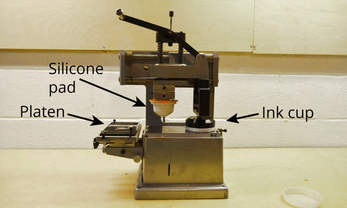
It’s a subject he’s written about here in the past, and he introduces it in the talk with a look at existing badge artwork and a mention of an expensive commercial inkjet process before considering the type of printing you see daily on the sides of promotional pens. Those company titles are deposited on pens using pad printing, an offset process in which ink is first deposited upon a photo-etched metal plate before being picked up on a silicone rubber pad for transfer to the object to be printed. It’s not the panacea for all coloured-PCB tasks, but for adding relatively small blocks of pigment to an otherwise monochromatic board it can be very successful.

The eye-catching Kiss -themed Tindie badges.

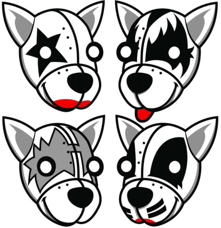
Brian’s examples are a panelised set of Tindie badges as a homage to the rock band Kiss, and his Tide pod addon containing a serial number in an EEPROM that was part of a Blockchain-inspired game. The Kiss Tindie badges use black soldermask with extensive white silkscreen and a modest area of red pad printing for the stage makeup, while the Tide addon makes clever use of the same swoosh printed in alternate colours at 180 degrees to each other.

In both cases there is some labour involved in creating the prints, and as his detailed write-up of printing the Tide pods reminds us, the process of creating the printing plate is not exactly an easy one. But it remains the best way yet to add extra colours to a board without paying a small fortune for the inkjet process, and if you’d like to put your own designs at the bleeding edge of PCB art you might wish to read his writeups and watch the video below the break.

This is just one example of the kind of manufacturing techniques, and electronic design principles on display at the Hackaday Superconference. There’s another Supercon just around the corner, so grab your ticket and send in your own talk proposal right away!

Continue reading “Hackaday Superconference: Pushing The Boundaries Of PCB Artwork With Brian Benchoff”

Improving A Conference Badge With 3D Printing

The obsession with over-the-top-hardware conference badges means that we as attendees get to enjoy a stream of weird and wonderful electronic gadgets. But for the folks putting these conferences on, getting a badge designed and manufactured in time for the event can be a stressful and expensive undertaking. To keep things on track, the designs will often cut corners and take liberties that you’d never see in commercial products. But of course, that’s part of their charm.

As a case in point, the OLED display on the 2019 KiCon badge is held on with just four soldered header pins, and can easily be bent or even snapped off. So [Jose Ignacio Romero] took it upon himself to develop a 3D printable mount which integrates with the PCB and gives the display some mechanical support. Any KiCon attendees who are looking to keep their badge in peak fighting condition for the long haul might want to start warming their extruders.

The design of this upgrade was made all the easier thanks to the fact that the KiCon badge is (naturally) open hardware. That meant [Jose] could import the PCB files directly into FreeCAD and have a virtual model of the badge to work with. This let him check the clearances and position of components without having to break out the calipers and measure the real thing.

Playing around with the virtual assembly, [Jose] quickly realized that the mounting holes in the OLED display don’t actually line up with the holes in the PCB; potentially why the screen didn’t get mounted on the final hardware. Once this misalignment was characterized, he was able to factor it into his design: the PCB side gets screwed down, and the screen snaps into printed “nubs” on the top of the mount.

Hackaday Editor-in-Chief [Mike Szczys] was on hand for KiCon 2019, and was kind enough to share the experience with those of us who couldn’t make it in person, including his own bout of hacking this very same badge.

Add-Ons Go Electroluminescent

It’s that time of the year again, and once more we’re faced with the latest innovations in Badgelife, the movement to explore the artistic merits of electronics and manufacturing. This is an electroluminescent printed circuit board, and it’s some of the finest work we’ve seen. It’s also a Shitty Add-On that glows blue.

The process for applying an electroluminescent coating to printed circuit boards is, surprisingly, something we’ve covered before. Late last year, [Ben Krasnow] delved deep into a DIY EL display. The process is expensive, but all the products come from a company called Lumilor. The first step in this process is applying a thin conductive coating on a substrate with an airbrush. Since the entire idea of printed circuit boards is to have a layer of conductive material etched into any shape you want, the simple circuit board is the idea experimental platform for playing with EL displays. Traditionally, EL displays were made entirely with a silk screen process, like [Fran]’s ongoing attempt to recreate the Apollo DSKY display.

The electronics for this badge are simply a Microchip MIC4832 EL Driver, which converts the 3.something volts from the add-on header into 100 or so Volts AC at hundreds of Hz. This is a single-chip solution to driving EL displays, and the only other parts you need are an inductor, diode, and a few caps and resistors. An ATtiny85 can be used to blink the circuits, or, alternatively, you could copy [Ben]’s work and build a character EL display.

The process of applying an electroluminescent coating to a PCB does require a spray gun or airbrush, and the chemicals are a bit expensive. This, though, is pushing the boundaries of what can be done with artistic PCBs. It’s new applications of technology, simply as wearable electronics. It’s the best example of the possibilities of the medium and some of the best work that’s come out of the Badgelife scene.

The Science Of Reverse Mounted LEDs

One of the most artistic applications of electrical engineering in recent memory is the burgeoning badgelife movement. This is an odd collective of people who are dedicating their time to rendering their own accomplishments in printed circuit boards. Of the entire badgelife collective, one of the most visible efforts are in Shitty Add-Ons, with a particular focus on reverse-mounted LEDs. Yes, you can install SMD LEDs upside down, and if you have your copper layers right, the light will shine through the badge.

One of the most prominent users of reverse mounted LEDs is [TwinkleTwinkie], and now finally we have a writeup on the science of reverse mounted LEDs. There’s a lot to unpack here, so buckle up and prepare to burn the tips of your fingers on a soldering iron.

For truly reverse-mounted PCBs, there are two options. The first, and most expensive, are ‘reverse gullwing’ LEDs. These LEDs are just like normal LEDs, except the SMD pads are reversed, allowing you to mount it so the light shines into the PCB. These LEDs are expensive, rare (only three companies make them), and they don’t really give off a lot of light. The other solution to reverse-mounting a LED is simply taking a standard 1206 SMD LED and manually soldering it upside-down. This is not pick and place friendly, although I’m sure you could find an LED manufacture that would put LEDs in reels upside-down if you want.

Side view LEDs

The takeaway for reverse mount LEDs is pick two: good, fast, or cheap. Reverse gullwing LEDs are expensive, but can be pick and placed and provide sufficient illumination. Hand-soldered LEDs installed upside down are cheap, slow, but also good.

But there is another option. Side view LEDs are a thing, and they can be pick and placed. You can get them in every color, and even UV. [Twinkle] has experimented with side-view LEDs in place of reverse mounted LEDs, and the results are promising. By putting the side view LED next to part of a PCB without copper or soldermask, there is some light bleed through the PCB. It’s somewhat uneven, but with a hot melt glue diffusor, you can get a somewhat decent bar of light being emitted through a PCB.

If you want to put blinky on a PCB, you have a lot of options. If you want to put blinky on a PCB without having any visible light source, these are your options. This is the state of the art in artistic PCBs, and we’re so glad [Twinkle] could share it with us.

Cyphercon Badge Has A Paper Tape Reader Built In

Cyphercon 4.0 came to life in Milwaukee, Wisconsin on Thursday and the conference badge is a brilliant and engaging design. At first glance it looks like a fairly mundane rectangular badge. But a closer look reveals simplistic elegance wrapping around some clever mechanical design and the awesome interactive mechanism of being able to read paper tape.

That’s right, this badge can read the series of holes punched in the long paper strips you normally associate with old iron of 50 years ago.

Continue reading “Cyphercon Badge Has A Paper Tape Reader Built In”

Introducing The Shitty Add-On V1.69bis Standard

The last few years have seen a rise of artistic PCBs. Whether these are one-off projects with a little graphic on the silkscreen or the art of manufacturing and supply chains, these fancy PCBs are here to stay. Nowhere is this more apparent than the loose confederation of Badgelife enthusiasts, a hardware collective dedicated to making expressive and impressive electronic baubles for various hacker conferences. Here, hundreds of different hardware badges are created every year. It’s electronic art, supported by a community.

Some of these badges aren’t technically badges, but rather small, blinky add-ons meant to connect to a main badge, and these add-ons are all backed by a community-derived standard. The Shitty Add-On Standard is how you put smaller PCBs onto bigger PCBs. It is supported by tens of thousands of badges, and all of the people who are spending their free time designing electronic conference badges are using this standard.

It’s been more than a year since the Shitty Add-On standard was created, and in that time the people behind the work have seen the shortcomings of the first edition of the standard. Mechanically, it’s not really that strong, and it would be neat if there were a few more pins to drive RGB LEDs. This has led to the creation of the latest revision of the Shitty Add-On Standard, V.1.69bis. Now, for the first time, this standard is ready for the world to see.

Continue reading “Introducing The Shitty Add-On V1.69bis Standard”

Jaromir Sukuba: The Supercon 2018 Badge Firmware

If you missed it, the Hackaday Supercon 2018 badge was a complete retro-minicomputer with a screen, keyboard, memory, speaker, and expansion ports that would make a TRS-80 blush. Only instead of taking up half of your desk, everyone at the conference had one around their neck, when they weren’t soldering to it, that is.

The killer feature of the badge was its accessibility and hackability — and a large part of that was due to the onboard BASIC interpreter. And that’s where Jaromir comes in. Once Voja Antonic had finalized the design of the badge hardware for our conference in Belgrade in the spring of 2018, as Jaromir puts it, “all we needed was a little bit of programming”. That would of course take three months. The badge was battle-tested in Belgrade, and various feature requests, speed ups, and bugfixes were implemented (during the con!) by Jaromir and others.

Firmware work proceeded over the summer. Ziggurat29 helped out greatly by finding ways to speed up the badge’s BASIC interpreter (that story is told on his UBASIC and the Need for Speed project page) and rolled into the code base by Jaromir. More bugs were fixed, keywords were added, and the three-month project grew to more like nine. The result: the badge was in great shape for the Supercon in the fall.

Jaromir’s talk about the badge is supremely short, so if you’re interested in hacking a retrocomputer into a PIC, or if you’ve got a badge and you still want to dig deeper into it, you should really give it a look. We don’t think that anyone fully exploited the CP/M machine emulator that lies inside — there’s tons of software written for that machine that is just begging to be run after all these years — but we’re pretty sure nearly everyone got at least into the basement in Zork. Dive in!

Continue reading “Jaromir Sukuba: The Supercon 2018 Badge Firmware”