Robot arm in Blender

Animate Your Robot In Blender

You’ve built a robot crammed full of servos and now you settle down for the fun part, programming your new dancing animatronic bear! The pain in your life is just beginning. Imagine that you decide the dancing bear should raise it’s arm. If you simply set a servo position, the motor will slew into place as fast as it can. What you need is an animation, and preferably with smooth acceleration.

You could work through all the math yourself. After half an hour of fiddling with the numbers, the bear is gracefully raising it’s arm like a one armed zombie. And then you realize that the bear has 34 more servos.

render of industrial robot type arm with pedestal, base, upperarm and lowerarm and IK ball

Fortunately for everybody who’s done the above, there’s Blender. It’s all about creating smooth motion for animations and computer graphics. Making robot motion with Blender is, if not easy, at least tolerable. We made a sample project, a 3-axis robot arm to illustrate. It has a non-moving pedestal, rotating base, upper arm, and lower arm. We’ll be animating it first in Blender and then translating the file over to something we can use to drive the servos with a little script.

Now, Blender is notorious for a difficult user interface. The good news is that, with revision 2.9, it moved to a much more normal interface. It still definitely is a large program, with 23 different editors and literally thousands of controls, but we’ll only be using a small subset to make our robot move. We won’t teach you Blender here, because there are thousands of great Blender tutorials online.  You want to focus on animation, and the Humane Rigging series is particularly recommended.

Continue reading “Animate Your Robot In Blender”

Moon moving from inside a large glass sphere into screens of two vintage television sets

Blending Pepper’s Ghost, Synths, And Vintage TVs

We were recently tipped off to the work of [Joshua Ellingson], and digging in, we found an extensive collection of art and ongoing experiments, with synthesizers deforming and driving old black-and-white clips played on vintage television sets, objects jumping from screens into the real world and back, and cathode ray tube oscilloscopes drawing graphics in the air (loud sound!) (nitter). It’s recommended that you check out the short showcase videos we embedded below before you continue reading, because transcribing these visuals into words won’t do them justice.

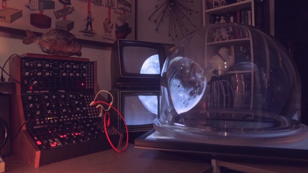
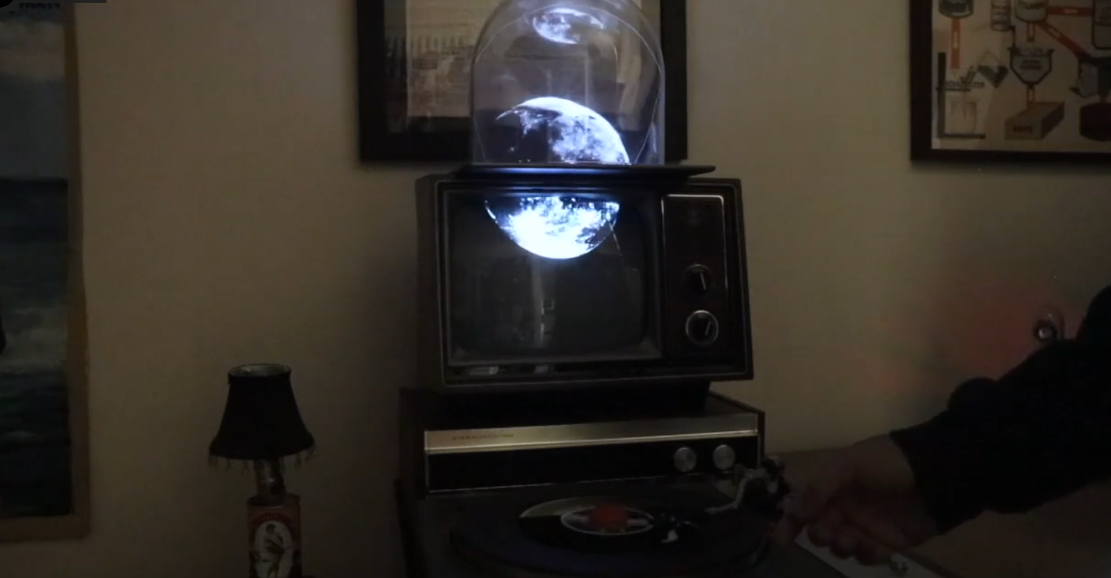
In case you’re not up for a video, however, we shall try transcribing them anyway. Animals, shapes and figures appear in the real world, bound by glass spheres and containers, using the technique known as Pepper’s Ghost. A variety of screens used for creating that illusion – sometimes it’s a tablet, and sometimes it’s an old television set rested upside down on top of a glass aquarium. Vintage television sets are involved quite often in [Ellingson]’s experiments, typically found playing movie scenes and clips from their appropriate eras, or even used as one of the locations that a Pepper’s Ghost-enchanted object could move into — firmly a part of the same imaginary world turned real.

It’s not always that things move from a TV screen into their glass boundary, gaining an extra dimension in the process, but when it happens, the synchronization is impeccable. All of that is backed by — and usually controlled by — Moog synthesizer sounds, knob turns driving video distortions or aspects of an object movement. Not all of his clips have synthesizers, old TVs, or Pepper’s Ghost illusion in them, but every experiment of his contains at least two out of these three, working in unison to create impressions. And as much as the art value is undeniable, [Ellingson] also adds a whole lot of hacker value for us to take away!

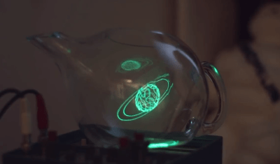
[Ellingson] understands what goes into building optical illusions like Pepper’s Ghost — using a variety of different glassware, from Erlenmeyer flasks to teapots, producing a consistent and ongoing stream of new ideas with unique spins on them. His aim is to share and create beyond what his art can achieve, which is why he encourages us to try it out ourselves — with this one minute video of a quick Pepper’s Ghost build, using nothing but a generic tablet, an emptied-out plastic snow globe and a piece of cheap transparency film used for school projectors. If you want to go beyond, he’s made an extensive tutorial on illusions of the kind he does, their simplicities and complexities, and all the different ways you can build one.

We all benefit when an artist finds a technology and starts playing with it, closing the divide between technology and art – and by extension, the divide between technology and nature. Sometimes, it’s flowing light art installations where you are a boulder in route of plankton’s movement, other times, it’s through-hole component-packed printed circuit birds that sing not unlike the non-printed-circuit ones, or manipulation of CRT displays with function generator-driven coils to offset the beam and turn the image into a pattern of lines.

Continue reading “Blending Pepper’s Ghost, Synths, And Vintage TVs”

Blender screen with CAD drawing

CAD Sketcher, It’s Parametric CAD For Blender

It’s very early days for CAD Sketcher, a new parametric CAD add-on for Blender by [hlorus], but it looks very promising.

We do a lot of 3D work and like Blender as an environment. It’s always annoying that Blender doesn’t do parametric modeling, so we’re forced into a dedicated CAD package. Blending the two for that robot ocelot is always particularly annoying.

CAD Sketcher lets the user make a ‘sketch’, a 2D drawing. They then  constrain it, saying “this line is vertical, that line is parallel to this one”, until the sketch is fully defined. It’s a normal part of parametric modelling. This is powerful when your model needs refined over and over.

There’s an old adage, “Better a tool that does 90% of the job well than one that does 100% poorly”. For CAD systems, (and much other software), we’d suggest “Better a tool that does 90% of the job well and works with whatever does the other 10%”.

3D render of gaurd
Guard Drawn In CAD Sketcher And Blender

We tried a test part, and being in Blender’s universe showed its value. CAD Sketcher doesn’t do bevels and rounds yet, and probably won’t for a while. But Blender’s perfectly happy doing them.

It’s not going to put SolidWorks out of business any time soon, but it’s a very promising new development. We hope it gathers some community and encourage contributions.

We cover CAD frequently, like the recent advances with CadQuery  and the port of OpenSCAD to WASM.

[thanks paulvdh]

Continue reading “CAD Sketcher, It’s Parametric CAD For Blender”

Texture Map GCode Directly In Blender With NozzleBoss

We’ve seen this funky dual disk polar printer already recently, but [Heinz Loepmeier] has been busy working on it, so here’s an update. The primary focus here is nozzleboss, a blender plugin which enables the surface textures of already sliced objects to be manipulated. The idea is to read in the gcode for the object, and convert it to an internal mesh representation that blender needs in order to function. From there the desired textures can be applied to the surfaces for subsequent stages to operate upon. One trick that nozzleboss can do is to create weight maps to tweak the extrusion flow rate or print velocity value according to the pixel value at the surface — such ‘velocity painting’ can produce some very subtle surface effects on previously featureless faces. Another 
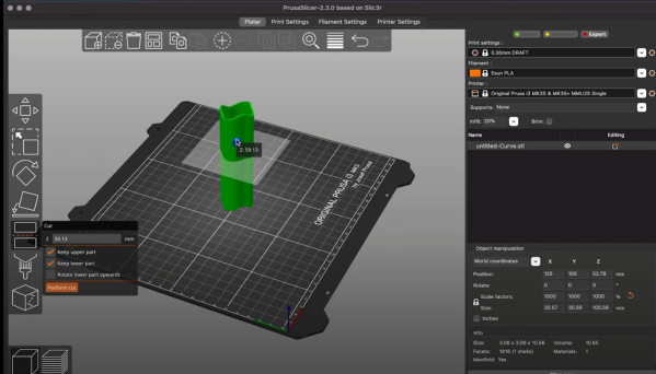
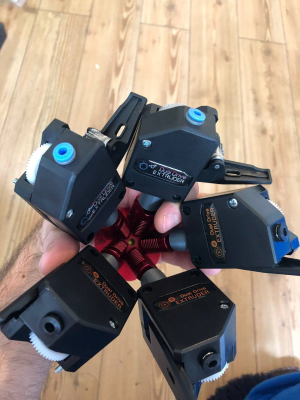
trick is to use the same weight maps and simply map colours to blender text blocks which are injected into the gcode at export time. These gcode blocks can be used swap tool heads or extruders, enabling blending of multiple filament colours or types in the same object.

Some nice examples of such printing manipulation can be seen on [Heinz’s] instagram page for the project. So, going back to the hardware again, the first video embedded below shows the ‘dual disk polar printer’ fitted with a crazy five-extruders-into-one-nozzle mixing hotend setup, which should be capable of full CMYK colour mixing and some. The second video below shows an interesting by-product of the wide horizontal motion range of the machine, that the whole printing area can be shifted to a nozzle at the other end of the gantry. This enables a novel way to switch extruders, by just moving the whole bed and print under the nozzle of interest! One final observation — is that of the print surface — it does look rather like they’re printing direct onto a slab of marble, which I think is the first time we’ve seen that.

Interesting printer designs are being worked on a lot these days, here’s a really nice 5-axis prusa i3 hack, and if you want to stay in the cartesian world, but your desktop machine is just too small, then you can always supersize it.

Continue reading “Texture Map GCode Directly In Blender With NozzleBoss”

Mirror, Mirror On The Wall, Do My Eyes Deceive Me After All

Say what you will about illusions, [Create Inc] has some 3D prints that appear to change shape when viewed in a mirror. For example, circles transform into stars and vice versa. A similar trick was performed by [Kokichi Sugihara] in 2016, where he showed circles that appear as squares in the mirror. For the trick to work, the camera’s position (or your eye) is important as the shapes look different from different angles. The illusion comes in when your brain ignores any extra information and concludes that a much more complex shape is a simpler one. [Create Inc] walks you through the process of how the illusion works and how it was created in Blender.

When he posted the video on Reddit, most seemed to think that it wasn’t a mirror and there was some camera trickery. At its heart, this is reverse-engineering a magic trick, and we think it’s an impressive one. STL files are on Thingiverse or Etsy if you want to print your own. We covered a second illusion that [Kokichi] did that relies on a similar trick.

Continue reading “Mirror, Mirror On The Wall, Do My Eyes Deceive Me After All”

Blender? No, Grinder

[Leandro Felipe] is no stranger to the dirty hack, and this video of his conversion of a blender into a handheld rotary grinding tool is no exception. (Embedded below.) But the end result is something pretty useful — a lighter and more maneuverable rotary grinder that’s got a lot more grunt to boot.

(The video is in Portuguese, but the captions work pretty well, once you get over the fact that the robots translate “grinding tool” as “rectifier” a lot of the time. And anyway, you’re here for the hacks.)

The highlights are a handmade coupling that mates the blender motor with the flexible shaft and chuck, purchased separately. And the flattened-out PVC pipe used as a mounting bracket. And him using the motor itself against a file to “lathe” down the drive shaft. And…

The tip of the day comes when he holds the blender motor in a metal vise to test it out. Metal and spinning magnets — what’s the worst that could happen?  Sparks, smoke, and a trip to the thrift store for another used blender.

If you just want to see the finished piece, you can jump ahead to the end. But it’s basically, get yourself a speed-adjustable blender, couple it to the shaft of an off-the shelf grinder, and you’re set.

It’s an idea so conceptually easy, you might wonder if Hackaday has ever showcased a blender dr3mel before. We have. What else can you power with a blender motor?

Thanks [Danjovic] for the tip!

Continue reading “Blender? No, Grinder”

Watch Blender Plugin Make Animated PCB Traces (and More)

[Staacks]’s Blender plugin to animate growth is behind the sweet animation seen above. It’s an add-on that cleverly makes creating slick growth animations easier when using Blender. It isn’t limited to PCB images either, although they do happen to make an excellent example of the process.

The add-on isn’t limited to animating PCB traces.

The idea is that one begins with an image texture with a structure showing a bunch of paths (like a maze, or traces on a PCB), and that gets used as an input. The plugin then uses a path finding algorithm to determine how these paths could grow from an origin point, and stores the relevant data in the color channels of an output image. That output is further used within Blender as the parameters with which to generate the actual animation, resulting in the neat self-creating PCB seen above. That PCB isn’t just for show, by the way. It’s the PCB for [Staacks]’s smart doorbell project.

Blender is an amazingly comprehensive tool for modeling and animation, and while we’ve covered using it to create high-quality KiCad renders, this kind of animation is really something else.

Here is the GitHub repository for the Blender growth tool if you’re interested in giving it a spin. If you’d like to see more first, watch the video embedded below for a showcase of what it’s capable of, and how it works.

Continue reading “Watch Blender Plugin Make Animated PCB Traces (and More)”