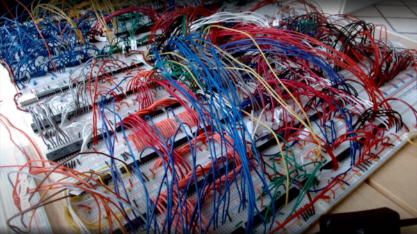
These pages have not been exactly devoid of home-built computers, with those constructed on solderless breadboard less frequent, but still not rarities. But what is more of a rarity is this ground-up 8-bit 74xx logic-based computer (video, embedded below) with full source, an emulator, assembler and test suite. [JDH] spent a solid couple of weeks working late into the night to build this, and the results show for themselves.
The new JDH-8 is now a figment of reality.
The architecture is a traditional 8-bit load/store microcoded processor with the microcode stored in easily programmable AT28C64 EEPROMs for ease of tweaking. The address bus is 16-bits, which is quite ample for this, and puts it in line with (admittedly more sophisticated) 8-bit micros of old such as the 6502. There is also a hardware stack, and a discrete-logic ALU as well! Finally, since that wasn’t enough work already, he added in his own discrete logic video controller.
There are sixteen instructions covering memory access, ALU operations and I/O operations. One of the great things about this project is that [JDH] readily admits the mistakes made along the way, and how the architecture didn’t need to be this complex. One example is that hardware stack wasn’t really necessary as it could just have been implemented in software. Also, due to the implementation, memory accesses were so fast compared with the achievable cycle time, that there really was no point to using load/store architecture at all! Still, [JDH] had fun building and programming it!
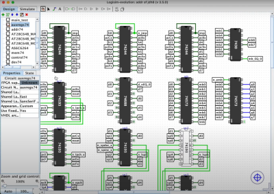
It was interesting to see the use of LogiSim-Evolution to debug first a high level model of the architecture and then the translation into TTL chips. This scribe wasn’t aware of that tool (the shame!) but is going to try this out real soon.
All code for the software side of things can be found on the project GitHub. Perhaps the hardware design will appear there as well, be at the time of writing we couldn’t seem to find it.
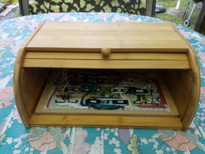
Can’t get enough breadboard computers? (We can’t) check this out from last year. Stuck for a suitable enclosure for your latest bread breadboard computer? How about a bread bin.
Continue reading “A Well Documented BreadBoard Computer Shows Dedication”
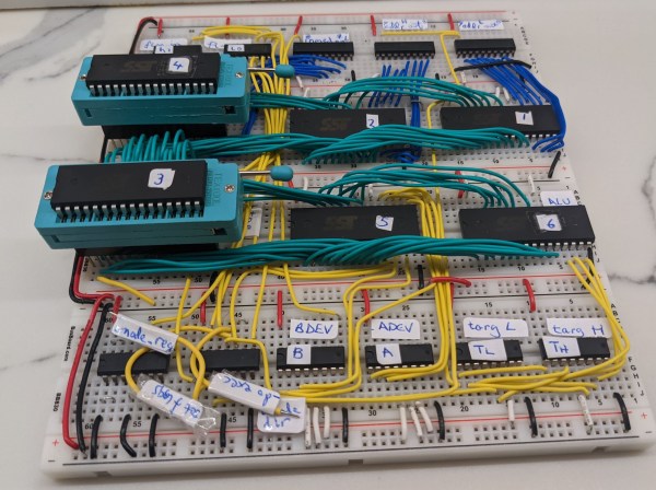
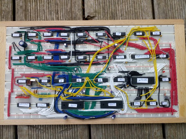
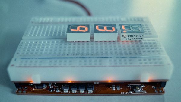
 The total circuit is incredibly compact for a complete CPU, using just 33 chips. This includes 64 KB of flash to store programs as well as a 555 timer to generate a clock signal. I/Os are limited to simple eight-bit input and output buses, but a sixteen-bit address bus gives it plenty of space to add ROM, RAM or fancier interfaces.