A Scratch-Built Drill Press Vise From Scrap

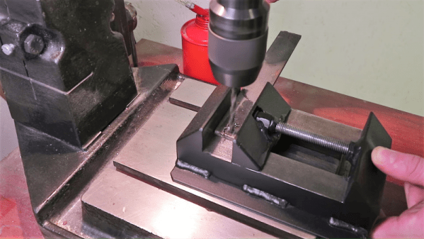
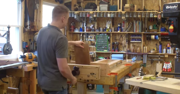
Never underestimate the importance of fixturing when you’re machining parts. No matter what the material, firmly locking it down is the key to good results, and may be the difference between a pleasant afternoon in the shop and a day in the Emergency Room. Flying parts and shattered tooling are no joke, but a lot of times quality commercial solutions are expensive and, well, commercial.  So this scratch-built drill press vise is something the thrifty metalworker may want to consider.

To be sure, [Ollari’s] vise, made as it is almost completely from scrap angle iron, is no substitute for a vise made from precision ground castings. But it’s clear that he has taken great care to keep everything as square and true as possible, and we give him full marks for maximizing his materials. And his tools — nothing more complicated than a MIG welder is used, and most of the fabrication is accomplished with simple hand tools. We like the way he built up sturdy profiles by welding strap stock across the legs of the angle iron used for the jaws, to give them a strong triangular cross-section to handle the clamping force. And using the knurled end of an old socket wrench as the handle was inspired; we’ll certainly be filing that idea away for a rainy day in the shop. Although we might use Acme rather than plain threaded rod.

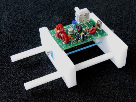
We always enjoy seeing someone fabricate their own tools, and this one reminds us a bit of the full-size bench vise built up from layers of welded steel we featured a while back. It even looks a little like this 3D-printed vise, too.

Continue reading “A Scratch-Built Drill Press Vise From Scrap”

Universal Quick-Release Bar Clamps

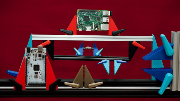
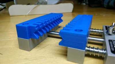
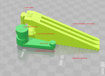
The typical hacker can never say no to more tools. And when it comes to clamps, one just can’t have enough of them. From holding small PCB’s to clamping together large sheets of plywood, you need a variety of sizes and quantities. So it would be pretty neat if we could just 3D print them whenever needed. [Mgx3d] has done that by designing 3D printable bar clamp jaws with a quick release mechanism that can be used with standard T-slot aluminum extrusion. This allows you to create ad-hoc bar clamps of any size and length quickly.

The design consists of two pieces – the jaw and its quick release lever, and does not require any additional parts or fasteners for assembly. Both pieces can be easily 3D printed without supports. The quick release lever is a simple eccentric cam design which locks the jaw in place by pushing down on the extrusion. The design is parametric and can be easily customized for different sizes, either in OpenSCAD or via the online customizer.  The online customizer supports Misumi 15 mm and 20 mm extrusion, 1″ 1010-S and 20 mm 20-2020 from 80/20 Inc., 15 mm from OpenBeam and 10 mm from MicroRax. But it ought to be easy to create fresh designs in OpenSCAD. Check out the video after the break to see the bar-clamps in action.

If you’d like to start equipping your shop with more 3D printed tools, look no further. We’ve featured many types over the years, such as the StickVise and its Gooseneck System, this 3D printed rubber band PCB Vise, and even a 3D printed Mini-Lathe.

Continue reading “Universal Quick-Release Bar Clamps”

PinJig Soldering Clamp Has Pins Seized By Airport Security

There’s an old adage that when performing a live demo, previously working hacks will mysteriously go awry. In this case, the hardware demo was doomed before it ever arrived at the conference.

PinJig is an interesting take on though-hole soldering. As its name indicates, it’s a jig which holds through-hole components in place as the board is flipped on its side (or even upside down). This is accomplished by 2000 steel pins which are locked in place after being nestled around all of the board’s components. Unfortunately, carrying this prototype onto an international flight didn’t work out. [Niall Barrett] told us that on his way from Ireland to Bay Area Maker Faire he was required to ditch the 3-inch steel pins that make up the jig, or not get on the plane.

Continue reading “PinJig Soldering Clamp Has Pins Seized By Airport Security”

Clamps, Cauls, And The Mother Of Invention

If there’s one thing you need in a woodshop, it’s more clamps. There are bar clamps, pipe clamps, spring clamps, and trigger clamps, but for one task in the workshop, no clamp does the job just right. Gluing up panels – a few wide pieces of wood joined on edge – either requires more clamps than you have or cauls, devices that press down on the boards vertically while the clamps press the board together horizontally.

[Andrew Klein] has just invented a new type of clamp for this task, proving once again that not all problems are solved, and there’s still some places where an invention can pop out of mid-air.

The new clamps are a modification to traditional bar clamps that allow for two clamps to interlock. On each of the ‘working’ ends of the clamps, there are two adjustment handles. The first screws the clamp horizontally, just like any bar or pipe clamp. The second adjustment handle moves a bearing up and down. When this bearing meshes with a riser on the mating end of another clamp, the two clamps are pressed together vertically.

The new clamps are effectively clamps and cauls, able to push material together from side to side and top to bottom. The new clamps work, too. In the video below, you can see [Andrew] gluing up a panel. When the vertical adjustment wheel is loosened, the boards come apart vertically. When the vertical adjustment wheel is tightened, the boards are perfectly in line with each other, both edge to edge and face to face.

Continue reading “Clamps, Cauls, And The Mother Of Invention”

Review: Stickvise Needs A Place On Your Bench

Stickvise is a simple device for a simple problem. It holds a work piece while you work on it. Most obviously this means a PCB for soldering, but there’s a twist of versatility that will make it work for a wide range of needs. Being someone who has often used the roll-of-solder-to-hold-a-circuit-board-down trick, only to upset the apple cart when I run out solder, this is a great little tool to have within arm’s reach. For those that already have a PCB vise, how often do you need more than one? How rarely do you need something that large? And if you’re lucky enough to have a microscope for soldering this is a perfect fixture for moving a board to and from without adjusting the focus.

Details of the Design

Simplicity. This is three pieces of aluminum bar-stock, some steel rod, nylon jaws, two springs, and some fasteners. It all works extremely well. To load up a new circuit board I loosen the wing nut and squeeze the clamp shut. Hand tightening the nut doesn’t take much force and it hasn’t slipped for me at all despite moving it around the bench for several days. Once set, the board can be taken out and flipped over easily thanks to the springs.

The extensibility here is key. As it stands, the nylon jaws have a V-groove to hold a board. If you need to support much taller boards you can always put some standoffs between the aluminum and the nylon jaws.

stickvise-custom-jaws
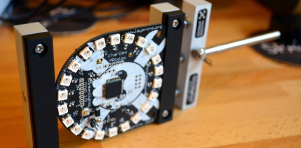
Better yet is the ability to design jaws for your own needs. [Alex Rich], Stickvise’s creator, already has a number of STL files available so that you may print out your own. The “fingers” on the custom jaw shown here interlock with the ones on the opposite side. But my favorite is an articulated set of “third-hand” style jaws based off of the PCB probe jig [Anool] covered back in May. There are even plans to make a parametric STL file so that printing larger or taller jaws doesn’t require a CAD modeling session.

If the range of the vise is too narrow you can simply replace the center bar with a longer one (source yourself or purchase from [Alex]) — the fixed aluminum end is secured with a set screw. This can even be used as a type of stretcher by reversing the spring jaw. I couldn’t think of an application in my own shop for this but you never know.

Stickvise Roots

stickvise-hackaday-approved
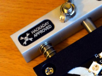
If you have an eagle eye you’ll have noticed the Jolly Wrencher with “Hackaday Approved” next to it on the Stickvise. When [Alex Rich] started refining his original design he posted about it as a project on Hackaday.io. It didn’t take long to grab our attention and, after tossing around the idea a bit we approached [Alex] about his plans for manufacturing and how Hackaday might figure into that. I love seeing hardware come to life like this; it puts an artisanal spin on the things I choose to have in my lab.

Conclusion

stickvise-angled

It’s so simple you could build it, but for me the production quality is well worth buying it instead. It’s simple and durable, with the ability to be specialized for a number of different purposes. I wish I had had it when populating the board I’ve been showing off in these pictures (the LayerOne Badge from this year). If you do any work with circuit boards at the bench the Stickvise is a solid entry on your must-have-tools list.

Cable Vise

New Cable-Based Vise Improves Woodworking Workshop

We are all aware of the typical wood shop vice, the type that is mounted underneath the workbench and takes forever to open and close by continuously spinning a large handle. These vises normally only open several inches due to the length of the operating screw. They are also not very wide because a cantilevered wide jaw would provide less force the further away it is from the center-mounted operating screw.

Cable Vise
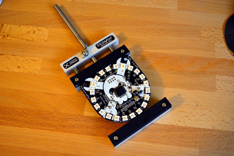
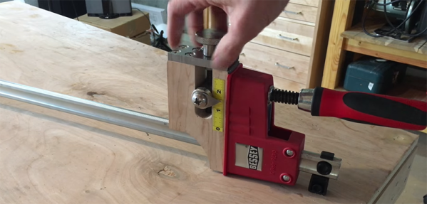
Wood worker [Andrew] wanted a very versatile and large vise for his shop. It needed to be wide, provide equal clamping force along the jaw and be able to hold very thick objects as well. One more thing, he wanted it to have a quick release clamping system so there would be none of that continuous handle spinning nonsense.

Spoiler Alert: [Andrew] did it! The end product is great but the interesting part is the journey he had taken along the way. There were 4 revisions to the design, each one making the vise just a bit better.

Continue reading “New Cable-Based Vise Improves Woodworking Workshop”

Simple PCB Vise

This one almost got relegated to a links post, but [Ken’s] simple PCB vise (PDF) is just so useful we had to give it a standalone feature. It works so well because he made every design feature count.

For instance, the groove the holds the PCB (almost impossible to see here but look at the diagrams in the PDF linked above) is cut with a dovetail bit, rather than just being a square rabbit. The clamping force is provided by that blue rubber band which simply hooks on a metal shelf peg on each side of the clamping plates. Those plates are machined out of polyethylene and slide nicely along the two nylon rods which keep them aligned. There’s really nothing to break or wear out here, except the rubber band with is easily replaceable. The rubber feet keep it from sliding across the bench as you work.

This is great for soldering, and would go right along with those diy smd parts clamps you made. It’s also a great way to hold onto your prototype boards when you’re working out the firmware.