Casting Machine Bases In Composite Epoxy

When you’re building a machine that needs to be accurate, you need to give it a nice solid base. A good base can lend strength to the machine to ensure its motions are accurate, as well as aid in damping vibrations that would impede performance. The problem is, it can be difficult to find a material that is both stiff and strong, and also a good damper of vibrations. Steel? Very stiff, very strong, terrible damper. Rubber? Great damper, strength leaves something to be desired. [Adam Bender] wanted to something strong that also damped vibrations, so developed a composite epoxy machine base.

[Adam] first takes us through the theory, referring to a graph of common materials showing loss coefficient plotted against stiffness. Once the theory is understood, [Adam] sets out to create a composite material with the best of both worlds – combining an aluminium base for stiffness and strength, with epoxy composite as a damper. It’s here where [Adam] begins experimenting, mixing the epoxy with sand, gravel, iron oxide and dyes, trying to find a mixture that casts easily with a good surface finish and minimum porosity.

With a mixture chosen, it’s then a matter of assembling the final mould, coating with release agent, and pouring in the mixture. The final result is impressive and a testament to [Adam]’s experimental process.

We’ve seen similar builds before — like this precision CNC built with epoxy granite — but detail in the documentation here is phenomenal.

Soluble Molds For Composite Parts

People have been experimenting with 3D printed molds for fiberglass and carbon fiber for a while now, but these molds really aren’t much different from what you could produce with a normal CNC mill. 3D printing opens up a few more options for what you can build including parts that could never be made on any type of mill. The guys at E3D are experimenting with their new dissolvable filament to create incredible parts in carbon fiber.

For the last year, E3D has been playing around with their new soluble filament, Scaffold. This is the water-soluble support material we’ve all been waiting for: just throw it in a bucket of warm water and it disappears. The normal use case for this filament is as a support material, but for these experiments in composites, E3D are just printing whole objects, covering them in carbon fiber prepreg, vacuum bagging them, and allowing them to cure. Once the carbon fiber isn’t floppy and gooey, the support material is dissolved in water, leaving a perfect composite part.

E3D aren’t that experienced with composites, so they handed a bit of filament off to So3D for some additional experimentation. The most impressive part (in the title pic for this post) is a hollow twisted vase object. This would have required a six-part machined mold and would have cost thousands of dollars to fabricate. Additional experiments of embedding ABS parts inside the Scaffold mold were extremely successful.

As you would expect, there are limitations to this process. Since E3D are using a dissolvable mold, this is a one-time deal; you’re not going to be pulling multiple composite parts off a 3D printed mold like you would with a machined mold. Curing the parts in a very hot oven doesn’t work — Scaffold filament starts to sag around 60°C. Using prepreg is recommended over dry fabric and resin, but that seems to be due more to the skill of the person doing the layup rather than an issue with materials.

A Car Stand Made Of Sand

When the guys at [Practical Engineering] say they have a dirty car stand, they really mean it! They made a block of dirt and sheets of fiberglass as reinforcement material, and the resistance was put to test by using it as a car stand. And yes, the block does the job without collapsing.

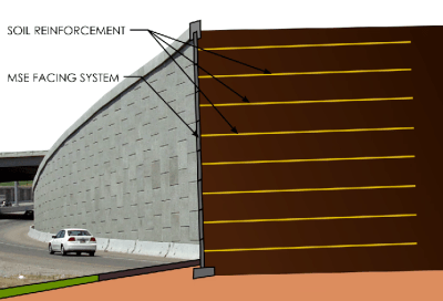
An exmple of MSE
A MSE structure. The lateral walls add no strength, they just look nice.

Soil is a naturally unstable material, it relies only on friction for structural stability, but it has a very low shear strength (the resistance of the material’s internal structure to slide against itself). Therefore, as soon as you put some weight, a soil structure fails. The trick is to form a composite by adding layers of a stiff material. Those layers increase the shear strength and you end up with an incredibly strong composite, or ‘mechanically stabilized earth‘ (MSE). You probably drive by some everyday, as in the picture at the right.

Even though the modern form of MSE was due to French engineer Sir Henri Vidal, reinforced soil has been used since the beginnings of human history, in fact, some sections of the Great Wall of China were made using this technique. [Practical Engineering] explanation and demonstration video is very well made, be sure to check it after the break. In case you don’t want to play with dirt next time you need to fix your car, you can always make a 3D printed jack.

Shape-Shifting Composite That You Can Make At Home

In material science, thermal expansion is a very well understood concept. However, in most cases it’s regarded as somewhat of a nuisance. It’s the kind of thing that gives engineers headaches, and entire subsystems of machines are often designed specifically to combat it. But a group of students at MIT have come up with an ingeniously simple way of taking advantage of thermal expansion to create shape-changing composites.

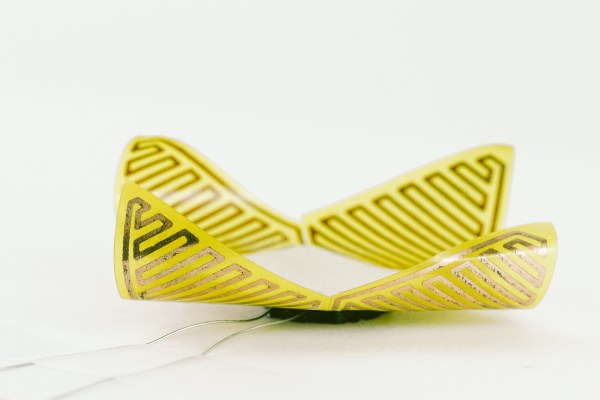
Their project is a method of creating shape-shifting composites, called uniMorph. It works by using resistive heating (or simply ambient temperature) to change the temperature of a sandwich composite. The composite is made of two different materials, and the copper traces to heat them. The two materials themselves aren’t particularly important, what’s important is that they have vastly different thermal expansion rates.

When the composite is heated, one material will expand more or less than the other material. Depending on the relative shapes of the two materials, this causes the composite to bend or twist in predetermined ways. How much it bends, for example, is just a matter of how the layers are cut, and how much they’re heated.

The concept itself isn’t exactly new – bimetallic composites have existed for ages. We even covered a similar idea that works based on moisture content. But, the methods used for uniMorph are very well thought out. It’s very inexpensive to produce, and the students seem to have devised reliable techniques for designing the layers in order to produce a desired shape change.

Continue reading “Shape-Shifting Composite That You Can Make At Home”

Upgrading The Battery In A Wrist PDA

No, your eyes do not deceive you. That’s a wrist-mounted PDA. Specifically, a Fossil Wrist PDA, also known as an Abacus, that was sold from 2003 to about 2005. Yep, it’s running PalmOS. [mclien] has had this watch/PDA for a while now, and found the original 180mAh battery wasn’t cutting it anymore. He made a little modification to the watch to get a 650mAh battery in this PDA by molding a new back for it.

The original PDA used a round Lithium cell, but being ten years old, the battery technology in this smart watch is showing its years. [mclien] found two batteries (380mAh and 270mAh) that fit almost perfectly inside the battery.

The new batteries were about 3mm too thick for the existing case back, so [mclien] began by taking the old case, adding a few bits of aluminum and resin, and making a positive for a mold. Two or three layers of glass twill cloth were used to form the mold, resined up, and vacuum bagged.

After many, many attempts, [mclien] just about has the case back for this old smartwatch complete. The project build logs are actually a great read, showing exactly what doesn’t work, and are a great example of using hackaday.io as a build log, instead of just project presentation.

Turning A Tiny CRT Into A Monitor

TV

[GK] picked up a few tiny 2″ CRTs a while back and for the longest time they’ve been sitting in a box somewhere in the lab. The itch to build something with these old tubes has finally been scratched, with a beautiful circuit with Manhattan style construction.

[GK] has a bit of a fetish for old oscilloscopes, and since he’s using an old ‘scope tube, the design was rather simple for him; there aren’t any schematics here, just what he could put together off the top of his head.

Still, some of [GK]’s earlier projects helped him along the way in turning this CRT into a monitor. The high voltage came from a variable output PSU he had originally designed for photomultiplier tubes. Since this is a monochrome display, the chrominance was discarded with an old Sony Y/C module found in a part drawer.

It’s a great piece of work that, in the words of someone we highly respect is, “worth more than a gazillion lame Hackaday posts where someone connected an Arduino to something, or left a breadboard in a supposedly “finished” project.” Love ya, [Mike].


Watch A Shop Tour Through The Screen Of An Oscilloscope

[Alan] posted a video tour of his electronics shop, but you’ll be viewing it through the green screen of an oscilloscope. The image above is a video camera filming a scope screen which displays the image of…. an oscilloscope (insert your own Yo Dawg meme here). But first he shares the technique he uses to display composite video on an oscilloscope screen.

The first three minutes of the video after the break are devoted to the video display hack. He starts with a glimpse of the breadboard circuit which takes the composite video signal and provides the necessary X, Y, and Z input signals to the scope to perform like this. He then walks through each portion of the schematic, which is based on an LM1881 video sync separator chip. The horizontal and vertical sync signals are separated by this chip, then filtered to produce ramp voltages for each to drive X and Y. The Z-axis is fed through a simple inverter circuit; Bob’s your uncle and your oscilloscope is now a TV monitor.

Of course this is not the first time this has been done. But we loved [Alan’s] presentation, and thought the shop tour was a fun way to finish off the video.

Continue reading “Watch A Shop Tour Through The Screen Of An Oscilloscope”