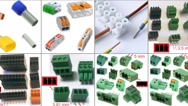
Wire Like A Pro: Peeking Into Wire Harness Mastery

There are many ways to learn, but few to none of them compare to that of spending time standing over the shoulder of a master of the craft. This awesome page sent in by [JohnU] is a fantastic corner of the internet that lets us all peek over that shoulder to see someone who’s not only spent decades learning the art of of creating cable harnesses, but has taken the time to distill some of that vast experience for the rest of us to benefit from.

Wire bundle

This page is focused on custom automotive and motorcycle modifications, but it’s absolutely jam-packed with things applicable in so many areas. It points out how often automotive wiring is somewhat taken for granted, but it shouldn’t be; there are hundreds of lines, all of which need to work for your car to run in hot and cold, wet and dry. The reliability of wiring is crucial not just for your car, but much larger things such as the 530 km (330 mi) of wiring inside an Airbus A380 which, while a large plane, is still well under 100 m in length.

This page doesn’t just talk about cable harnessing in the abstract; in fact, the overwhelming majority of it revolves around the practical and applicable. There is a deep dive into wiring selection, tubing and sealing selection, epoxy to stop corrosion, and more. It touches on many of the most common connectors used in vehicles, as well as connectors not commonly used in the automotive industry but that possess many of the same qualities. There are some real hidden gems in the midst of the 20,000+ word compendium, such as thermocouple wiring and some budget environmental sealing options.

There is far more to making a thing beyond selecting the right parts; how it’s assembled and the tools used are just as important. This page touches on tooling, technique, and planning for a wire harness build-up. While there are some highly specialized tools identified, there are also things such as re-purposed knitting needles. Once a harness is fully assembled it’s not complete, as there is also a need for testing that must take place which is also touched on here.

Thanks to [JohnU] for sending in this incredible learning resource. If this has captured your attention like it has ours, be sure to check out some of the other wire harness tips we’ve featured!

splice-cad assembly

Splice CAD: Cable Harness Design Tool

Cable harness design is a critical yet often overlooked aspect of electronics design, just as essential as PCB design. While numerous software options exist for PCB design, cable harness design tools are far less common, making innovative solutions like Splice CAD particularly exciting. We’re excited to share this new tool submitted by Splice CAD.

Splice CAD is a browser-based tool for designing cable assemblies. It allows users to create custom connectors and cables while providing access to a growing library of predefined components. The intuitive node editor enables users to drag and connect connector pins to cable wires and other pinned connectors. Those familiar with wire harnesses know the complexity of capturing all necessary details, so having a tool that consolidates these properties is incredibly powerful.

Among the wire harness tools we’ve featured, Splice CAD stands out as the most feature-rich to date. Users can define custom connectors with minimal details, such as the number of pins, or include comprehensive information like photos and datasheets. Additionally, by entering a manufacturer’s part number, the tool automatically retrieves relevant data from various distributor websites. The cable definition tool is equally robust, enabling users to specify even the most obscure cables.

Once connectors, cables, and connections are defined, users can export their designs in multiple formats, including SVG or PDF for layouts, and CSV for a detailed bill of materials. Designs can also be shared via a read-only link on the Splice CAD website, allowing others to view the harness and its associated details. For those unsure if the tool meets their needs, Splice CAD offers full functionality without requiring an account, though signing in (which is free) is necessary to save or export designs. The tool also includes a version control system, ideal for tracking design changes over time. Explore our other cable harness articles for more tips and tricks on building intricate wire assemblies.

Continue reading “Splice CAD: Cable Harness Design Tool”

All About USB-C: Connector Mechanics

There’s two cases when hackers have to think about USB-C connector mechanics. The first is when a USB-C connector physically breaks, and the second is when we need to put a connector on our own board. Let’s go through both of them.

Clean That Connector

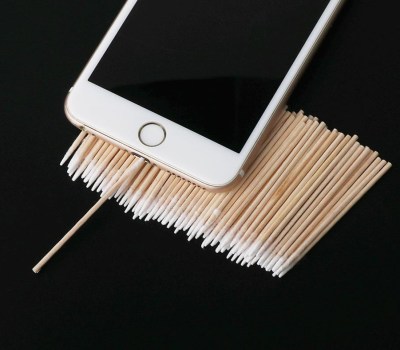
What if a socket on your phone or laptop fails? First off, it could be due to dust or debris. There’s swabs you can buy to clean a USB-C connector; perhaps adding some isopropyl alcohol or other cleaning-suitable liquids, you can get to a “good enough” state. You can also reflow pins on your connector, equipped with hot air or a sharp soldering iron tip, as well as some flux – when it comes to mechanical failures, this tends to remedy them, even for a short period of time.

How could a connector fail, exactly? Well, one of the pins could break off inside the plastic, or just get too dirty to make contact. Consider a device with a USB-C charging and data socket, with USB 2.0 but without high-speed pairs – which is to say, sadly, the majority of the phones out there. Try plugging it into a USB-A charger using a USB-A to USB-C cable. Does it charge, even if slowly? Then, your VBUS pins are okay.

Plug it into a Type-C charger using a Type-C cable, and now the CC pins are involved. Does it charge in both orientations? Then both of your CC pins are okay. Does it charge in only one orientation? One of the CC pins has to be busted. Then, you can check USB 2.0 pins, used for data transfer and legacy charging. Plug the phone into a computer using a USB-A to USB-C cable. Does it enumerate as a device? Does it enumerate in both orientations? If not, you might want to clean D- and D+ pins specifically, maybe even both sets. Continue reading “All About USB-C: Connector Mechanics”

A Simple Web-Based Wiring Harness Tool

When building electronic assemblies there is quite often the need to construct custom cables to hook things up. It’s all very well if you’re prototyping by hand, or just building one or two of a thing, but if you’re cranking them out using outside help, then you’re going to want to ensure that cable is described very accurately. [Christian Nimako-Boateng Jr.] presents for us the first version of wirely, a wiring harness tool. This is a web-based tool that allows one to describe the cable ends and connectivity between them, producing a handy graphic and exports to excel in a format that should be easy to follow.

Based around the wireviz Python library running on a flask-based backend, image data are sent to the web assembly front-end and rendered with OpenGL. Configuration files can be imported and exported as JSON, making it easily linkable to other tools if required. Helpfully, the tool also seems to support some kind of revision control, although we didn’t try that yet. The process is straightforward enough, one simply defines a few groups (these relate to individual PCBs or other floating items in the assembly) which each contain one or more connectors. First, the connectors are described with part numbers, and wire gauge data, before defining the list of connections (wires) showing which signal and physical pins are connected together. Nothing more complex than that yet. We think there is still some more functionality that the tool could manage, such as shielding and guarding details, twisted pair definitions and a few others, but for a first pass, wirely looks pretty handy.

If you want a more heavyweight option using IEC 60617 symbols for describing wiring harnesses, then look no farther than QElectroTech, and yes, we have covered wireviz before, just for those that want to cut out the middleman and describe their cables in Python directly.

Remoticon 2021 // Debra Ansell Connects PCB In Ways You Didn’t Expect

“LEDs improve everything.” Words to live by. Most everything that Debra Ansell of [GeekMomProjects] makes is bright, bold, and blinky. But if you’re looking for a simple string of WS2812s, you’re barking up the wrong tree. In the last few years, Debra has been making larger and more complicated assemblies, and that has meant diving into the mechanical design of modular PCBs. In the process Debra has come up with some great techniques that you’ll be able to use in your own builds, which she shared with us in a presentation during the 2021 Hackaday Remoticon.

She starts off with a quick overview of the state of play in PCB art, specifically of the style that she’s into these days: three dimensional constructions where the physical PCB itself is a sculptural element of the project. She’s crossing that with the popular triangle-style wall hanging sculpture, and her own fascination with “inner glow” — side-illuminated acrylic diffusers. Then she starts taking us down the path of creating her own wall art in detail, and this is where you need to listen up. Continue reading “Remoticon 2021 // Debra Ansell Connects PCB In Ways You Didn’t Expect”

USB to Dupont adapter by [PROSCH]

USB Power Has Never Been Easier

USB cables inevitably fail and sometimes one end is reincarnated to power our solderless breadboards. Of course, if the cable broke once, it is waiting to crap out again. Too many have flimsy conductors that cannot withstand any torque and buckle when you push them into a socket. [PROSCH] has a superior answer that only takes a couple of minutes to print and up-cycles a pair of wires with DuPont connectors. The metal tips become the leads and the plastic sheathing aligns with the rim.

The model prints with a clear plus sign on the positive terminal, so you don’t have to worry about sending the wrong polarity, and it shouldn’t be difficult to add your own features, like a hoop for pulling it out, or an indicator LED and resistor. We’d like to see one with a tiny fuse holder.

If you want your breadboard to have old-school features, like a base and embedded power supply, we can point you in the right direction. If you are looking to up your prototyping game to make presentation-worthy pieces, we have a host of ideas.

What’s In A USB-C Connector?

Anyone who’s ever put together a bill-of-materials for an electronic device will be familiar with the process of scouring supplier catalogs and data sheets for the best choice of components. The trick is to score the best combination of price and performance for the final product, and for those unused to the process, there are always seemingly identical products with an astonishingly wide variety of prices. It’s a topic [Timon] explores in a Twitter thread, examining a 20-cent in quantity of 100 USB-C socket alongside one that costs only 5 cents, and his teardown provides a fascinating insight into their manufacture.

The parts look so nearly identical that while it’s possible to differentiate between them visually, it’s near impossible to work out which was the cheaper. Some tiny features such as a crack in a metal fold or a bit less plating on the contacts emerge, but even then it’s no guide to the quality as they don’t appear on the same part. It’s only when the metal shell is removed to expose the underlying plastic moulding that more clues emerge, as one moulding is more complex than the other. The more complex moulding provides a better and more reliable fit at the expense of a much more costly moulding process, so at last we can not only identify the more expensive part but also see where the extra cash has gone. It’s a subtle thing, but one that could make a huge difference to the performance of the final assembly and which makes for a fascinating expose for electronic design engineers.

If connectors are your thing, there’s a wealth of fascinating information in their history.