When Difference Matters: Differential Signaling

We have talked about a whole slew of logic and interconnect technologies including TTL, CMOS and assorted low voltage versions. All of these technologies have in common the fact that they are single-ended, i.e. the signal is measured as a “high” or “low” level above ground.

This is great for simple uses. But when you start talking about speed, distance, or both, the single ended solutions don’t look so good. To step in and carry the torch we have Differential Signalling. This is the “DS” in LVDS, just one of the common standards throughout industry. Let’s take a look at how differential signaling is different from single ended, and what that means for engineers and for users.

Single Ended

Collectively, standards like TTL, CMOS, and LVTTL are known as Single Ended technologies and they have in common some undesirable attributes, namely that ground noise directly affects the noise margin (the budget for how much noise is tolerable) as well as any induced noise measured to ground directly adds to the overall noise as well.

By making the voltage swing to greater voltages we can make the noise look smaller in proportion but at the expense of speed as it takes more time to make larger voltage swings, especially with the kind of capacitance and inductance we sometimes see.

Differential

diff4

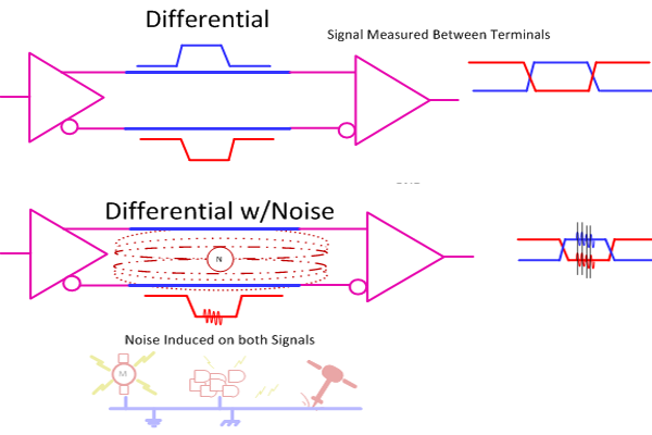
Enter Differential Signaling where we use two conductor instead of one. A differential transmitter produces an inverted version of the signal and a non-inverted version and we measure the desired signal strictly between the two instead of to ground. Now ground noise doesn’t count (mostly) and noise induced onto both signal lines gets canceled as we only amplify the difference between the two, we do not amplify anything that is in common such as the noise.

Continue reading “When Difference Matters: Differential Signaling”

A Better Way To Plug A CPLD Into A Breadboard

If you read my first post about a simple CPLD do-it-yourself project you may remember that I seriously wiffed when I made the footprint 1” wide, which was a bit too wide for common solderless breadboards. Since then I started over, having fixed the width problem, and ended up with a module that looks decidedly… cuter.

To back up a little bit, a Complex Programmable Logic Device (CPLD) is a cool piece of hardware to have in your repertoire and it can be used to learn logic or a high level design language or replace obsolete functions or chips. But a CPLD needs a little bit of support infrastructure to become usable, and that’s what I’ll be walking you through here. So if you’re interested in learning CPLDs, or just designing boards for them, read on!

Continue reading “A Better Way To Plug A CPLD Into A Breadboard”

Antti Lukats: The Past, Present, And Future Of Programmable Logic

[Antti] has gained a bit of a reputation over on Hackaday.io – he has a tremendous number of FPGA projects on hackaday.io, and they’re all open source. If you’re looking for street cred with FPGAs, [Antti] has it. His Hands-on experience with FPGAs and CPLDs stretches back to the very first chips in the 70s. We’re so happy that he’s working to share this depth of knowledge, and that includes this talk he gave a few weeks ago at the Hackaday SuperConference. Take a look and then join us after the break for an overview of the FPGA terrain, then and now.

Continue reading “Antti Lukats: The Past, Present, And Future Of Programmable Logic”

Not Ready For FPGAs? Try A CPLD

[Kodera2t]  wanted to experiment with programmable logic. Instead of going with an FPGA board, he decided to build his own CPLD (complex programmable logic device) board, with a built-in programmer. The CPLD is a Xilinx 9536 which is inexpensive and, though obsolete, still readily available. The programmer for the board uses an FT232RL and the total cost is very low ([kodera2t] says it is in the price range of a Raspberry Pi Zero or about $4).

From a user’s point of view, a CPLD is just a small FPGA. Internally, there is a significant difference in how they implement your design. Although there are differences between different product families, CPLDs usually use a sea of logic gates arranged as an AND/OR chain. By feeding inputs and inverted inputs into the AND gates and then ORing the results, you can build interesting logic circuits. However, modern CPLDs use Verilog or VHDL, so you describe what you want just like with an FPGA and the software figures out how to use the underlying circuits to give you what you want.

Continue reading “Not Ready For FPGAs? Try A CPLD”

Build An AM Radio Transmitter From A CPLD

[Alex Lao] has been playing around with the CPLD-like parts of a PSoC. Which is to say, he’s been implementing simple logic functions “in hardware” in software. And after getting started with the chip by getting accustomed to the different clock sources, he built a simple AM radio that transmits at 24 MHz.

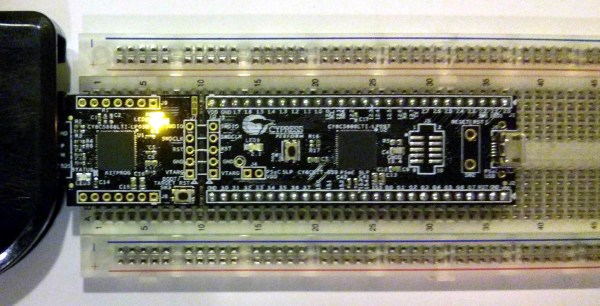
The device that [Alex] is learning on is a Cypress PSoC 5LP, or more specifically their (cheap) prototyping kit for the part. The chip itself is an ARM microprocessor core with a CPLD and some analog tidbits onboard to make interfacing the micro with the outside world a lot easier. [Alex] doesn’t even mess around with the microprocessor, he’s interested in learning the CPLD side of things.

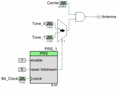
PRS-CircuitHe starts off with a 24 MHz carrier and a 1 kHz tone signal, and combines them with a logical AND function. When the tone is on, the carrier plays through; that’s AM radio at its most elemental. Everything is logic (square waves) so it’s a messy radio signal, but it’ll get the job done.

Adding a multiplexer up front allows [Alex] to play two tones over his “radio” station. Not bad for some simple logic, and a fantastic Hello World project for a CPLD. We can’t wait to see what [Alex] is up to next!

If you’re interested in getting your feet wet with either CPLDs in general or a CPLD + micro system like Cypress’s, the development kit that [Alex] is using looks like a cheap and painless way to start. (Relatively speaking — PSoCs are a step or two up a steep learning curve from the simpler 8-bit micros or an Arduino.) Hackaday’s own [Bil Herd] has a video on getting started with another member of the Cypres PSoC family, so you should also check that out.

Programmable Logic: Build Yourself A CPLD Module

A Complex Programmable Logic Device (CPLD) is a great piece of hardware to have in your repertoire. As its name implies, you can program these chips to serve the logic functions you need. This might be replacing an obsolete chip, or maybe just a way to learn and try different techniques. What better way to learn than to get your hands on a CPLD and give it a try?

I created a CPLD module with the intent of being able to plug it into lots of things including solderless breadboards, but I screwed up. It seems that the plugin space available on a solderless breadboard is 1.1”, I had made the footprint 1” wide leaving no room for a row of wires on both sides. Duh.

But let me back up and show more about what I’m doing , I wanted to make a programmable piece of logic that could be built as a kit one could easily solder at home, could be programmed in-circuit, and could work at 3.3 or 5 volts.

Image5bTo implement an easily solderable kit I went with an older CPLD part that also has 3.3v and 5v versions that will maintain its programming regardless of power. The logic itself is a CPLD IC from the Altera Max family with two versions that fit the board with either 32 or 64 macrocells. A macrocell is the basic logic building block and it is programmed with logic “terms” and then interconnected to other macrocells through a programmable interconnect.

Continue reading “Programmable Logic: Build Yourself A CPLD Module”

Hackaday Prize Entry: An Open Source Graphics Card

For last year’s Hackaday Prize, [PK] tried to build a video card for microcontrollers and headless Linux systems. It was only 640×480 resolution VGA, but the entire project was designed around a CPLD communicating with a microcontroller over SPI. This prize entry was, by [PK]’s own admission, a failure. It was late, but now he’s had an entire year to perfect his design. That means he can enter version two of his VGATonic in The Hackaday Prize.

The VGATonic version 2 uses a Xilinx XC95144XL CPLD for the VGA timing, and an ATTiny 2313a to read the SPI bus. Video memory is four megabits of static RAM. That’ls pretty much all you need for the most basic VGA graphics card, and all of this is packed onto a 3×3 inch PCB.

You can do a lot with 640×480 8-bit graphics running at 25FPS. In the video below, [PK] has a ‘hello world’ of sorts, Doom, running on a Raspberry Pi 2 with his SPI graphics card. Yes, it’s a graphics card for the Raspberry Pi, and it looks really good.

Further refinements of the design will include some primitive graphics routines. Not OpenGL or anything fancy, just something to reduce the number of writes on the SPI bus. It’s a great project, and perfect if you want to add video out to an Intel Galileo or other microcontroller project. [PK] has a video demo, you can check that out below.


The 2015 Hackaday Prize is sponsored by:

Continue reading “Hackaday Prize Entry: An Open Source Graphics Card”