Electronic Etch-A-Sketch, No Microcontroller Required

In a lot of ways, Etch-A-Sketch is the perfect toy; simple, easy to use, creative, endlessly engaging, and as a bonus, it’s completely mechanical. We find that last attribute to be a big part of its charm, but that’s not to say an electronic version of the classic toy can’t be pretty cool, especially when it’s done without the aid of a microcontroller.

This is one of those “because I can” projects that we always find so interesting, and more so because it wasn’t entirely clear to [BigZaphod] that he had the skills to pull it off. While his initial design centered around a bunch of 8×8 LED matrix displays and a 256×4-bit RAM chip, the rest of it was a lot of hand-waving. After a few experiments with addressing the LEDs, [Zaphod] started filling in the blanks with a refresh circuit using a 555 — naturally — and a pair of counters. Properly debounced encoders for the horizontal and vertical controls came next, along with more counters to track the cursor and a host of other circuits that ended up looking like a “one of each” selection from the 7400-series catalog.

While we do wish for a schematic on this one, it’s still a pretty enjoyable video, and the end product seems to work really well. The electronic version has a few features the original lacks, such as wrapping the cursor to the other side of the screen. We’d imagine that the buttons on the encoders could be put to work, too; perhaps a click could make it so you can move the cursor without leaving a trail behind. That might be a challenge to execute in logic, but then again, that was the point of the whole thing.

Still jonesing for that mechanical Etch-A-Sketch experience? Not a problem.

Continue reading “Electronic Etch-A-Sketch, No Microcontroller Required”

I2C Bus Splitting With A More Professional Touch

Last week, I covered some of the bitter details of an interesting hack that lets us split up the I²C clock line into multiple outputs with a demultiplexer, effectively giving us “Chip Selects” for devices with the same address.

This week, I figured it’d be best to layout a slightly more practical method for solving the same problem of talking to I²C devices that each have the same address.

I actually had a great collection of comments mention the same family of chips I’m using to tackle this issue, and I’m glad that we’re jumping off the same lead as we explore the design space.

Recalling the Work of Our Predecessors

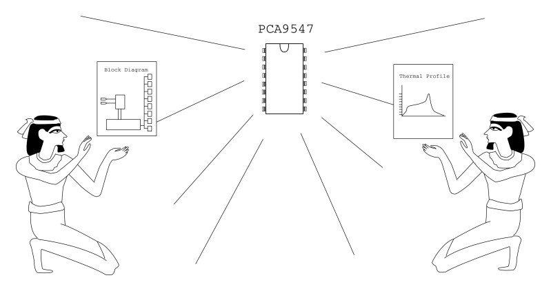
Before figuring out a clever way of hacking together our own solution, it’s best to see if someone before us has already gone through all of the trouble to solve that problem. In this case–we’re in luck–so much that the exact bus-splitting behavior we want is embedded into a discrete IC, known as the PCA9547.

chip_reverence

It’s worth remembering that our predecessors have labored tirelessly to create such a commodity piece of silicon.

The PCA9547 (PDF) is an octal, I²C bus multiplexer, and I daresay, it’s probably the most practical solution for this scenario. Not only does the chip provide 8 separate buses, up to seven more additional PCA9547s can be connected to enable communication with up to 64 identical devices! What’s more, the PCA9547 comes with the additional benefit of being compatible with both 3.3V and 5V logic-level devices on separate buses. Finally, as opposed to last week’s “hack,” each bus is bidirectional, which means the PCA9547 is fully compliant with the I²C spec.

Selecting one of the eight I²C buses is done via a transfer on the I²C bus itself. It’s worth mentioning that this method does introduce a small amount of latency compared to the previous clock-splitter solution from last week. Nevertheless, if you’re planning to read multiple devices sequentially from a single bus anyway, then getting as close-as-possible to a simultaneous read/write from each device isn’t likely a constraint on your system.


With a breakout board to expose the pads, I mocked up a quick-n-dirty Arduino Library to get the conversation started and duplicated last week’s demo.

Happily enough, with a single function to change the bus address, the PCA9547 is pretty much a drop-in solution that “just works.” It’s definitely reassuring that we can stand on the shoulders of our chip designers to get the job done quickly. (They’ve also likely done quite a bit more testing to ensure their device performs as promised.) Just like last week, feel free to check out the demo source code up on Github.

Until next time–cheers!

Giving An Old Arm New Life

[Jarek] found a non-functional robotic arm sitting around and wanted to get it working again. By adding a few custom boards to an Arduino he managed to do just that.

The arm is driven by six stepper motors, each having four control wires. To handle all of these [Jarek] used TIP120 transistors to protect the controller. This still leaves the problem of 24 control wires to connect. By using a couple of 74HC4514 demultiplex chips he cut that number down to just 8 Arduino control pins. He completed the project by interfacing an original Playstation controller as the input device.

Source code for the project is available for download but we didn’t see a schematic for his setup. This shouldn’t be a problem as the low parts count should mean the datasheets for the transistors and demultiplexers are all you really need.