Make Dual Pin Header Footprints Into Breadboard Friendly DIP

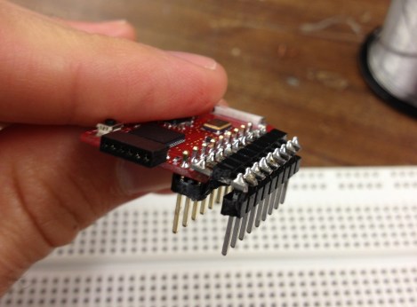
[John] wrote in with a solution to a prototyping issue that has vexed us for quite some time. Above you can see the DIP friendly solution for dual-row pin headers which he came up with. With just a bit of easy soldering he now has a breadboard friendly device for prototyping.

He starts by soldering a dual row pin header on the board, then clips off all of the legs on the outside row. The row of legs that remain are then inserted into one side of the trench on his breadboard. The other side of the trench has a single row pin header, and he solders them to the outer row on the breakout board using another single pin header aligned horizontally. This isn’t a 100% convenient solution, as it’s still pretty hard to get your jumper wires in the breadboard on the side covered by the breakout board. But if you plan in advance you can place your wires first, then plug in the development board.

Here [John] is working with TI’s eZ430-RF2500 board. We’d like to go back and remove the dual pin socket we soldered on our eZ430-F2013, replacing it with this style of pins.

Turning A 600 Mil Chip To 300 Mil

We’ve seen a few builds featuring NXP’s LPC1114 microcontroller before. This chip – the only breadboard friendly ARM microcontroller available – comes in a ‘still a little too large for prototyping’ 600 mil, 28 pin package. We won’t hazard a guess why NXP chose this rather large package, but the good news is it’s possible to shave this chip down to the more common 300 mil, 28-pin package used by AVRs and PICs.

In the video tutorial of this procedure, the chip is first taped down to a desktop CNC mill. 150 mil on each side of the die are removed, exposing the very cool-looking pattern of leads coming out of the chip. This isn’t enough area to solder, so the chip had to be further milled to expose some of the internal wiring.

After soldering everything to a set of pins, the new 300 mil package is covered in epoxy putty, milled down again into a nice cube shape and painted. Yes, the modified chip does work, and no, we can’t figure out why NXP chose a 600 mil package for this microcontroller over the far more common 300 mil chip.

Video after the break. Tip ‘o the hat to [Ian] for sending this one in.

Continue reading “Turning A 600 Mil Chip To 300 Mil”

The Easiest Way To Dive In To ARM Programming

[Brad] has been very excited about an ARM Cortex-M0 chip released by NXP; it’s a fully featured ARM microcontroller, and is, quite amazingly, stuffed into a hobbyist and breadboard-friendly DIP-28 package. After finding a supplier for this chip, [Brad] dove in and put together a great tutorial for programming an ARM on the breadboard using open source tools.

The chip in question is NXP’s LPC1114FN28, a 28-pin breadboard friendly chip we’ve posted about before. After finding a single supplier for this microcontroller (only $1.26 for one chip!), [Brad] pulled out his breadboard and started wiring things up.

Because this microcontroller has an on-board oscillator, wiring up a breadboard and putting in a breakout for an FTDI cable was a snap. After configuring a toolchain and writing a bit of code, the only issue was uploading the code to the chip. This was handled by the lpc21isp programming tool, slightly modified and configured by [Brad] to support his favorite microcontroller.

The LPC1114FN28 is an impressive bit of kit, and with free tools to program the damn thing, we can’t wait for a homebrew ARM dev board to show up.

Cutting Out Your Own Breakout Boards

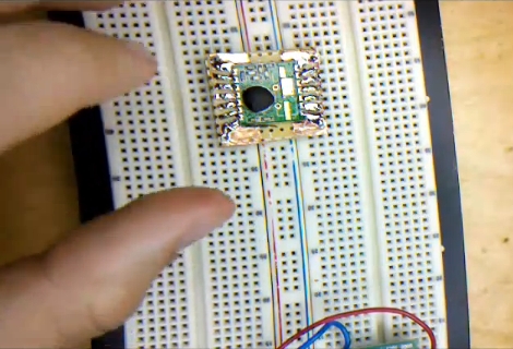
[Caleb] needed to use some surface mount components when prototyping. Instead of buy a breakout board he made one himself without doing any etching. The process he shows off in the video after the break uses copper tape to layout the traces for the board. It’s quite an interesting method which requires a sharp knife and a steady hand.

He used regular protoboard as a substrate and applied a layer of copper tape on the side without copper pads. From there he poked holes for the DIP pin headers. Now it’s time to do some cutting. [Caleb] removed the band of copper that would fall in between the pins of the surface mount device. He then tacked it in place with one dot of solder and drew the traces from the part to the pin headers. After removing the part he cut out the waste in between each line he drew with marker. What he’s left with is a set of thin traces that connect each pin of the surface mount component to the corresponding through-hole pin header.

This is very time-consuming, but then again so is soldering jumper wires to small-pitch components.

Continue reading “Cutting Out Your Own Breakout Boards”

Automated Chip Burning

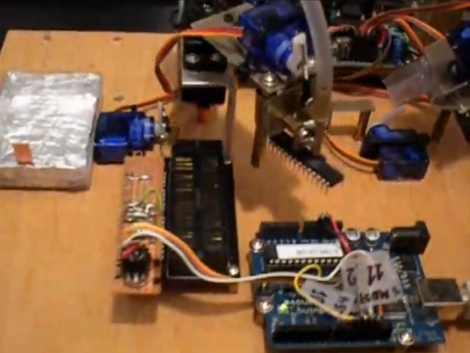
[Alexsoulis] needed to burn the Arduino bootloader to a slew of ATmega328 chips. Instead of sitting there and plugged the chips into a programmer one at a time, he build a robotic microcontroller programmer.

It starts with the DIP package microcontrollers in a tube, with a servo motor to dispense them one-by-one. An arm swings over and picks up the chip with a fish pump powered vacuum tweezers similar to the pick-and-place head we saw recently. From there the chip is dropped into a ZIF socket and programmed by an Arduino. Once the process is complete it is moved to the side and the process repeats.

We’ve reported on using an Arduino as an AVR programmer but we’ve never actually done it ourselves (we use an AVR Dragon programmer). Take a look at the video after the break and let us know if you think the actual programming seems incredibly slow.

Continue reading “Automated Chip Burning”

DuinoStamp


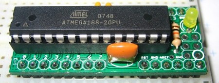
We think that in honor of the DuinoStamp’s small size and big power, the post about it should also be small and powerful. About the size of 34-pin DIP, the DuinoStamp is a breakout board that fits in DIP sockets and is Arduino compatible. It features an ATmega 168-20PU chip, a 16MHz resonator, decoupling capacitors and more. It doesn’t come with the necessary 5V power supply or any kind of interface cable, but what do you expect for under $10?