We’ve got a thing for projects that have no real practical value but instead seek to answer a simple yet fundamental question: I wonder if I can do that? This dead-bug style 555 blinky light is one of those projects, undertaken just to see how small a circuit can be. Pretty small, as it turns out, and we bet it can get even smaller.
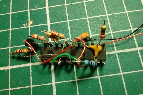
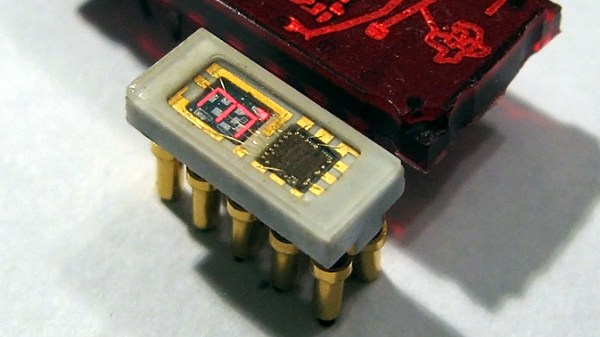
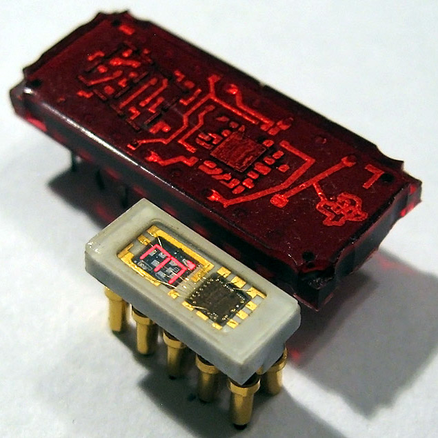
[Danko]’s minimal circuit is about as small as possible for the DIP version of the venerable 555 chip. The BOM is stripped to the bone: just the chip, three resistors, a capacitor, and an LED. All the discrete components are SMDs in 0805. The chip’s leads are bent around the package to form connections, and the SMDs bridge those “traces” to complete the circuit. [Danko] shows the build in step-by-step detail in the video below. There’s some fairly fine work here, but we can’t help wondering just how far down the scale this could be pushed. We know someone’s made a smaller blinky using a tiny microcontroller, but we’d love to see this tried with the BGA version of the chip which is only 1.4 mm on a side.
Cheers to [Danko] for trying this out and having some fun with an old chip. He seems to have a bit of a thing for the 555; check out this cute robot sculpture that’s built around the chip.
Continue reading “Minimal Blinky Project Makes The Chip The Circuit Board”
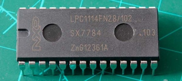
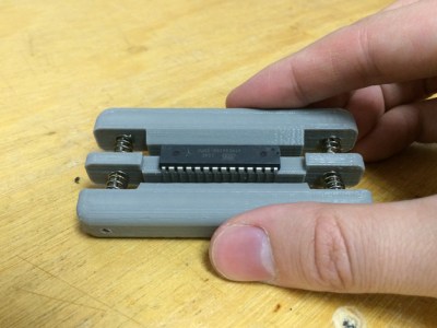 Fresh from the factory Dual Inline Package (DIP) chips come with their legs splayed every so slightly apart — enough to not fit into the carefully designed footprints on a circuit board. You may be used to imprecisely bending them by hand on the surface of the bench. [Marco] is more refined and shows off a neat little spring loaded tool that just takes a couple of squeezes to neatly bend both sides of the DIP, leaving every leg the perfect angle. Shown here is
 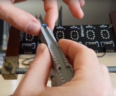 Another tool which caught our eye is the one he uses for bending the metal film resistor leads: the “Biegelehre” or lead bending tool. You can see that [Marco’s] tool has an angled trench to account for different resistor body widths, with stepped edges for standard PCB footprint spacing. We bet you frequently use the same resistor bodies so 3D printing is made easier by