Four Years Of Learning ESP8266 Development Went Into This Guide

The ESP8266 is a great processor for a lot of projects needing a small microcontroller and Wi-Fi, all for a reasonable price and in some pretty small form factors. [Simon] used one to build a garage door opener. This project isn’t really about his garage door opener based on a cheap WiFi-enabled chip, though. It’s about the four year process he went through to learn how to develop on these chips, and luckily he wrote a guide that anyone can use so that we don’t make the same mistakes he did.

The guide starts by suggesting which specific products are the easiest to use, and then moves on to some “best practices” for using these devices (with which we can’t argue much), before going through some example code. The most valuable parts of this guide especially for anyone starting out with these chips are the section which details how to get the web server up and running, and the best practices for developing HTML code for the tiny device (hint: develop somewhere else).

[Simon] also makes extensive use of the Chrome developers tools when building the HTML for the ESP. This is a handy trick even outside of ESP8266 development which might be useful for other tasks as well. Even though most of the guide won’t be new to anyone with experience with these boards, there are a few gems within it like this one that might help in other unrelated projects. It’s a good read and goes into a lot of detail about more than just the ESP chips. If you just want to open your garage door, though, you have lots of options.

Hacking This Smart Bulb Is Almost Too Easy

The regular Hackaday reader no longer needs to be reminded about how popular the ESP8266 is; they see the evidence of that several times a day. But what might not be quite so obvious is that it isn’t just us hacker types that are in love with the inexpensive IoT microcontroller, it’s also popping up more and more frequently in commercial products.

As [Majenko] demonstrates, one of those ESP-powered devices is the LOHAS Smart LED Bulb. Upon cracking one open, he found that these relatively low-cost bulbs are little more than a standard ESP8266 chip and a couple of LED drivers. He wanted to see how hard it would be to get his own code running on the bulb, and by the looks of it, it took longer to get the thing open then it did to load it up with a custom firmware.

The bulb’s PCB features the aforementioned ESP8266, a 1MB 25Q80 flash chip, and MY9231 LED drivers. Whoever put the board together was nice enough to label the RX, TX, and GPIO test points, though [Majenko] notes that what’s labeled as 3.3 V appears dead. With a ESP-01 programmer wired up to the board and the appropriate board settings (which he provides), you can use the Arduino IDE to upload whatever you like to it.

Running “Hello World” on a smart bulb is fun and all, but what about kicking on those LEDs? [Majenko] found a library that works with the MY9231 drivers, and it didn’t take long to figure out which of the ESP’s pins were used to communicate with them. All in all, he said it was far easier than he expected.

You’ll probably want to put this bulb back into service after reprogramming, so [Majenko] advises caution when cracking open the shell. There are clips holding on the diffuser which he assures us are going to break no matter what you do, plus some silicone adhesive. He suggests super glue to hold it together when you’re done programming it, and using an OTA firmware so you don’t need to get back in there.

In the past we’ve shown how some hackers are rolling their own smart bulb hardware, but with cheap commercial offerings that are so easily hackable, it frankly doesn’t seem worth the effort. On the other hand, an influx of cheap ESP-powered bulbs isn’t all good news.

Squeezebox Comes To The ESP

Streaming music may now come from somewhere in the cloud to an app on your phone and be sent to the client built in to almost every entertainment device you own, but there was a time when the bleeding edge lay in dedicated streaming device that connected to your existing set-up. One of the players in this market was Logitech with their Squeezebox line of products, and while the original hardware may have been discontinued it remains very much alive among its dedicated userbase due to the free nature of the Logitech Media Server software and implementations of the slimproto streaming protocol in players. Now you can create a network player on about as cheap hardware as it is possible to find, because [Bgiraut] has produced a client for the ESP32 and ESP8266.

The software can be found on GitHub, and comes with the warning that it’s an early proof-of-concept rather than a polished release. It has two options for playback that both require a little bit of extra hardware, an I2S DAC for uncompressed streams or a VS1053 codec module for compressed ones, but neither of those need be expensive.

You can find Logitech Media Server from its download page, and give this device a try. Meanwhile we’ve covered many Squeezebox implementations, including ones on the Raspberry Pi, and the PogoPlug.

Thanks [joyofdivisions] for the tip.

WiFi Your Door Lock With An ESP

The Internet of Things is upon us, and with that comes a deluge of smart cameras, smart home monitors, and smart home locks. There actually aren’t many smarts in these smart conveniences, and you can easily build your own. That’s what [MakerMan] did with some off-the-shelf parts and just a little bit of code. Now he can open his door with WiFi, and it’s a nice clean build.

The build process began by first removing the existing barrel bolt on the door. This was replaced by a deadbolt that also had some really neat solenoids inside for remote activation. This was mounted to the door in a way that the door could lock, with a minimal amount of damage from some skillful hacksaw work. The only thing left to do after this was add some electronics and brains to the lock.

For this, [MakerMan] added a button and LED to the outside of the door. Some of these wires were fed into the lock mechanism, with a few more run over to a project enclosure mounted next to a power outlet. The project enclosure holds an ESP-8266, power regulator, and relay board, and the ESP is running code that instantiates a web server that will unlock the door with a few clicks on a web page.

Sure, it’s probably not the most secure lock on the planet, and the 5V linear regulator is held on to the relay board with hot glue, but this is an exceptionally well-documented project, and all the code is available in an archive.

Continue reading “WiFi Your Door Lock With An ESP”

RemoteDebug For ESP Platforms

Debugging tools are critical to quick and effective development. Without being able to peek under the hood at what’s really going on, it can be difficult to understand and solve problems. Those who live on the Arduino platform are probably well acquainted with using the serial port to debug, but it’s far from the only way. [JoaoLopesF] has coded the RemoteDebug tool for ESP platforms, and the results are impressive.

RemoteDebug does away with the serial interface entirely, instead using the ESP’s native wireless interface to send debug data over TCP/IP. It’s all handled over telnet, making it completely platform agnostic. By handling things over the WiFi connection, it negates issues with physical access, as well as hassles with cables and limited serial ports. It’s also of benefit to robotics projects, which no longer need a tether when debugging.

It comes with a similar set of features to [JoaoLopesF]’s earlier work, SerialDebug. Things like verbosity and timestamps are all built in, making it easy to get high-quality debug data without having to reinvent the wheel yourself. Video after the break.

Continue reading “RemoteDebug For ESP Platforms”

Building An ESP8266 Doorbell On Hard Mode

It certainly seems as though it should be an easy enough project; all [Miguel De Andrade] wanted was to receive a notification when somebody was pressing his doorbell, and thought it would be a good project to get his feet wet in the wonderful world of ESP8266 hacking. But as fate would have it, not everything went according to plan. In the end he got it sorted out, but it’s an interesting look at how even the “easy” projects can call the gremlins out of hiding.

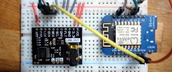
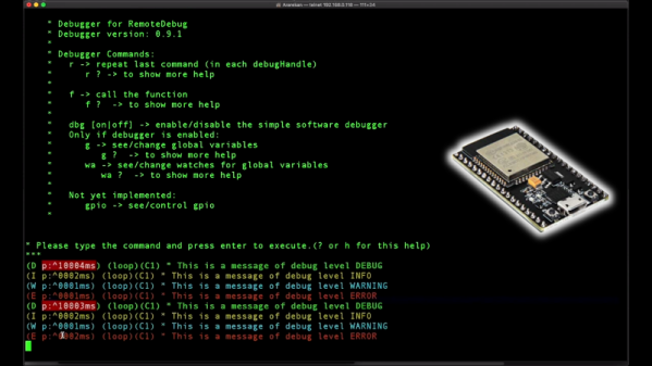
Arguably, the problems started when [Miguel] picked up an ESP-01 module from a local electronics retailer. While the convenience of buying the hardware in a brick and mortar store can’t be overstated, it did mean he was stuck with a slightly more spartan experience compared to the more common ESP “development boards”. Programming it externally with a Teensy ended up not being much of an obstacle, but it did mean he was stuck with only two GPIO pins.

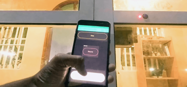
At any rate, with ESP in hand, the next step was figuring out how the existing bell and intercom system even worked. Unfortunately, after some experimentation [Miguel] found there was a bit more going on there than he’d hoped. According to his multimeter, the one line from the intercom sits at approximately 5 VDC when it’s open, and drops down to 2.5 VDC when pressed. If that wasn’t bad enough, picking up the handset to answer the intercom sent the voltage up to a microcontroller-killing 12 VDC. To complicate maters further, the supply line for the intercom was 23 VAC, so he’d need to rectify that somehow if he wanted to avoid a separate power supply for the ESP.

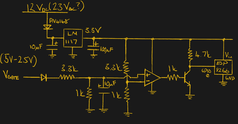
To turn this jumble of voltages into a nice clean 0 – 3.3 V signal for the ESP8266, he came up with a circuit based around the LM358 comparator that utilizes an LM117 regulator to power itself and the ESP at the same time. A couple of diodes are there to block the AC component from causing trouble, and an A2N2222A transistor is used as a buffer amplifier to boost the output of the comparator so it registers as a digital HIGH on the ESP. The circuit took a bit of fiddling to get sorted out, but in the end [Miguel] says it seems to get the job done.

You might think the problems were solved, but this is where it gets really annoying. The system would work fine for awhile, and then inexplicably go silent. In diagnosing the problem he realized that his circuit connected to GPIO_0 was inadvertently putting the ESP8266 into programming mode, since it was holding the pin LOW unless the intercom button was pressed. He assumed he could just move the circuit to the other GPIO pin, but as that one has the board’s LED on it, that caused its own problems. For now, [Miguel] hasn’t come up with a solution to this issue, and has learned to live with the fact that the system won’t come back up cleanly should it lose power for any reason.

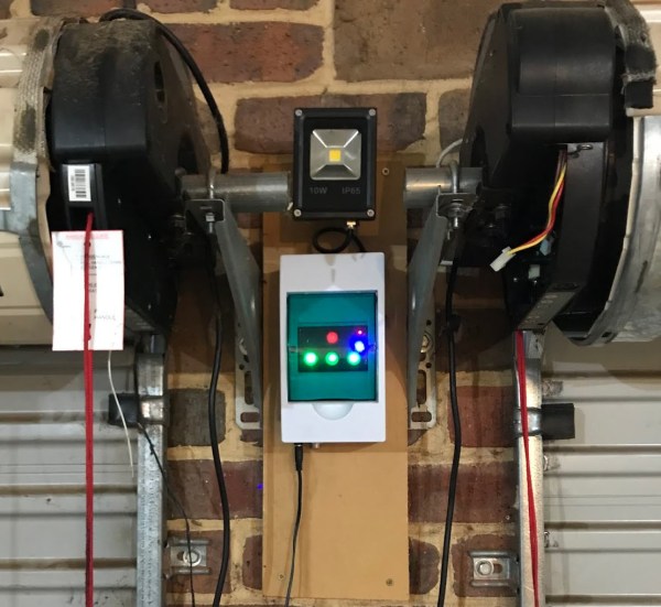
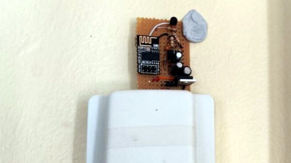
If you’re looking for a slightly classier look than a scrap of perfboard stuck on the wall with what appears to be chewing gum, we’ve also seen the ESP8266 used in some more ornate doorbell setups. Of course if you still haven’t gotten your head wrapped around the whole Internet-connected button thing, you can always start with something a little easier.

Wiring The ESP-32 To Ethernet

Since its introduction years ago, the ESP-8266 has taken over the world. It’s the chip inside thousands of different projects, and the basis for dozens of different IoT thingamadoos. The follow-up to the 8266, the ESP-32, is even more capable. It has a ton of peripherals inside, including an Ethernet MAC. What’s that? Yes, it’s possible to put Ethernet on an ESP-32, and give an IoT board PoE. That’s what [Patrick] is doing for his Hackaday Prize project, and it’s an awesome idea.

This build began as you would expect, with an ESP-32 module attached to one side of a board with some breakouts for the GPIOs and a USB to Serial chip. The tricky part here is the PoE part of the Ethernet, which requires MagJack Ethernet connectors, a flyback transformer, and a PoE-PD controller. These were expensive parts, and the design of such a board requires some thinking — you need isolation across the transformer, and proper ground planes for this mess.

There’s something slightly brilliant about using an ESP-32 in a wired configuration. Far too often, we see these modules used as wireless nodes in a sensor net. The battery consumption is significant, and all those makers are adding USB power input to their fancy WiFi sensor nets. If you’re running wires for power anyway, why not add Ethernet and do away with all that mucking around with WiFi setup. It’s a great project, and one of the better entries in this year’s Hackaday Prize.