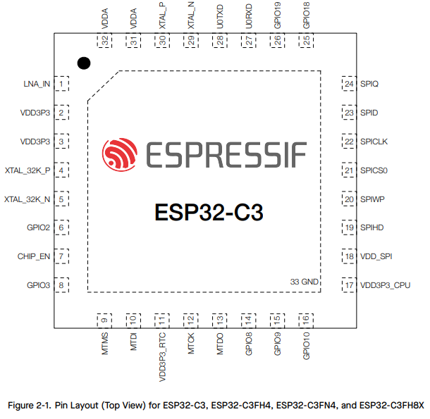
A clear acrylic cylinder is shown, inside of which plants are visible. There is mist inside the tube, and LEDs light it from above. A black plastic cap to the tube is visible.

Preserve Your Plants With An Automated Terrarium

For those of us who aren’t blessed with a green thumb and who are perhaps a bit forgetful, plants can be surprisingly difficult to keep alive. In those cases, some kind of automation, such as [Justin Buchanan]’s Oasis smart terrarium, is a good way to keep our plants from suffering too much.

The Oasis has an ultrasonic mister to water the plants from a built-in tank, LED grow lights, fans to control airflow, and a temperature and humidity sensor. It connects to the local WiFi network and can set up recurring watering and lighting schedules based on network time. Most of the terrarium is 3D-printed, with a section of acrylic tubing providing the clear walls. Before installing the electronics, it’s a good idea to waterproof the printed parts with low-viscosity epoxy, particularly since the water tank is located at the top of the terrarium, where a leak would drip directly onto the control electronics.

Continue reading “Preserve Your Plants With An Automated Terrarium”

Simple Antenna Makes For Better ESP32-C3 WiFi

We’ve seen tons of projects lately using the ESP32-C3, and for good reason. The microcontroller has a lot to offer, and the current crop of tiny dev boards sporting it make adding a lot of compute power to even the smallest projects dead easy. Not so nice, though, is the poor WiFi performance of some of these boards, which [Peter Neufeld] addresses with this quick and easy antenna.

There are currently a lot of variations of the ESP32-C3 out there, sometimes available for a buck a piece from the usual suspects. Designs vary, but a lot of them seem to sport a CA-C03 ceramic chip antenna at one end of the board to save space. Unfortunately, the lack of free space around the antenna makes for poor RF performance. [Peter]’s solution is a simple antenna made from a 31-mm length of silver wire. One end of the wire is formed into a loop by wrapping it around a 5-mm drill bit and bending it perpendicular to the remaining tail. The loop is then opened up a bit so it can bridge the length of the ceramic chip antenna and then soldered across it. That’s all it takes to vastly improve performance as measured by [Peter]’s custom RSSI logger — anywhere from 6 to 10 dBm better. You don’t even need to remove the OEM antenna.

The video below, by [Circuit Helper], picks up on [Peter]’s work and puts several antenna variants to further testing. He gets similarly dramatic results, with 20 dBm improvement in some cases. He does note that the size of the antenna can be a detriment to a project that needs a really compact MCU and tries coiling up the antenna, with limited success. He also did a little testing to come up with an optimal length of 34 mm for the main element of the antenna.

There seems to be a lot of room for experimentation here. We wonder how mounting the antenna with the loop perpendicular to the board and the main element sticking out lengthwise would work. We’d love to hear about your experiments, so make sure to ping us with your findings.

Continue reading “Simple Antenna Makes For Better ESP32-C3 WiFi”

A light-up clock displays the day of the week.

What Day Is It Again? Check The Clock

If you’re lucky enough to work from home, you’ll soon find that it presents its own set of challenges, mostly related to work/life balance. It can get so bad that you don’t know what day of the week it is. Really. Ask us how we know.

Rather than miss a meeting (or a day off), prolific hacker [Arnov Sharma] created this day of the week clock. It uses a customized LED driver board with seven sets of three LEDs, each driven by a MOSFET. Each MOSFET is controlled by a DFRobot Mini Beetle ESP32-C3. It runs on a 2200 mAh, 3.7 V lithium-ion battery.

While this is mostly PCBs, there are three printed parts that turn it into a displayable object. We really like the look of this clock — it has just the right amount of pizazz to it and reminds us of a and old movie marquee. Be sure to check out the great build instructions.

We love a good clock around here. In case you missed it, here is the latest from [Moritz v. Sivers] that uses a caustic lens to display the time.

A small mood/busy indicator attached to a laptop.

Personal Traffic Light Stops Them In Their Tracks

Working from home can be pretty cool, but if you’re not the only one in the house trying to do it, the whole situation can feel like you’re right back in the office with all those walking, talking distractions. Except they’re in pajamas instead of business casual.

The parts needed to build this mood indicator.So, what’s the answer? Many times it’s not practical to stop what you’re doing, especially just to communicate that you’re busy. We suppose you could glare at them, put up your hand, or even give a dismissive wave, but a better solution might be this mood signal built by [gokux].

Through a simple web app, you can be red to indicate that you’re super busy, yellow to mean busy-ish, and green for let’s gossip about the cats.

This mood indicator is built on the Seeed Xiao ESP32-C3 and shows the given mood indicator on a small matrix of sixteen WS2812B LEDs. It’s powered by a 600 mAh, 3.7 V battery and a small push button switch. As usual, [gokux] has grade-A instructions for building your own version of this slick solution.

Would you like something more tactile and low-tech? Check out our own [Bob Baddeley]’s free/busy indicator from the lockdown days.

Little Quadruped Has PCB Spine And No Wiring

Dealing with all the wiring can quickly become a challenge on robots, especially the walking variety which have actuators everywhere. [Eric Yufeng Wu] sidestepped the wiring issue by creating Q8bot, a little quadruped where all the components, including the actuators, are mounted directly on the PCB.

[Eric] uses a custom PCB as the spine of the robot, and the eight servos plug directly into connectors on the PCB. With their bottom covers removed, the servos screw neatly into a pair of 3D printed frames on either side of the PCB, which also have integrated 14500 battery holders. The PCB is minimalist, with just the XIAO ESP32C3 module, a boost converter circuit to drive the servos, and a battery fuel gauge. Each SCARA-style leg consists of four SLS 3D printed segments, with press-fit bearings in the joints.

The little one moves quickly, and can even do little jumps. For this prototype, most of the control processing is done on a laptop, which sends raw joint angles to the onboard ESP32 via the ESP-Now protocol. We think this little robot has a lot of development potential, and fortunately [Eric] has made all the hardware and software files available for others to build their own.

Continue reading “Little Quadruped Has PCB Spine And No Wiring”

Building An IR Thermometer That Fits On Your Keychain

Non-contact infrared (IR) thermometers used to be something of an exotic tool, but thanks at least in part due to the COVID-19 pandemic, they’re now the sort of thing you see hanging up near the grocery store checkout as a cheap impulse buy. Demand pushed up production, and the economies of scale did the test. Now the devices, and the sensors within them, are cheap enough for us hackers to play with.

The end result is that we now have projects like this ultra compact IR thermometer from [gokux]. With just a handful of components, some code to glue it all together, and a 3D printed enclosure to wrap it all up, you’ve got a legitimately useful tool that’s small enough to replace that lucky rabbit’s foot you’ve got on your keys.

If this project looks familiar, it’s because the whole thing is closely related to the LiDAR rangefinder [gokux] put together last month. It shares the same Seeed Studio XIAO  ESP32-C3 microcontroller, 0.49 inch OLED display, and tiny 40 mAh LiPo battery. The only thing that’s really changed, aside from the adjustments necessary to the 3D printed enclosure, is that the LiDAR sensor was replaced with a MLX90614 IR temperature sensor.

[gokux] has put together some great documentation for this build, making it easy for others to recreate and remix on their own. Assembly is particularly straightforward thanks to the fact that both the display and temperature sensor communicate with the ESP32 over I2C, allowing them to be wired daisy chain style — there’s no need for even a scrap of perfboard inside the case, let alone a custom board.

Showing a Raspberry Pi 4 board connected to an ESP32 devboard using jumper wires for the purposes of this project

ESP-Hosted Turns ESP32 Into Linux WiFi/BT Adapter

While we are used to USB WiFi adapters, embedded devices typically use SDIO WiFi cards, and for good reasons – they’re way more low-power, don’t take up a USB port, don’t require a power-sipping USB hub, and the SDIO interface is widely available. However, SDIO cards and modules tend to be obscure and proprietary beyond reason. Enter ESP-Hosted – Espressif’s firmware and driver combination for ESP32 (press release)(GitHub), making your ESP32 into a WiFi module for either your Linux computer (ESP-Hosted-NG) or MCU (ESP-Hosted-FG). In particular, ESP-Hosted-NG his turns your SPI- or SDIO-connected ESP32 (including -S2/S3/C2/C3/C6 into a WiFi card, quite speedy and natively supported by the Linux network stack, as opposed to something like an AT command mode.

We’ve seen this done with ESP8266 before – repurposing an ESP8089 driver from sources found online, making an ESP8266 into a $2 WiFi adapter for something like a Pi. The ESP-Hosted project is Espressif-supported, and it works on the entire ESP32 lineup, through an SDIO or even SPI interface! It supports 802.11b/g/n and even Bluetooth, up to BLE5, either over an extra UART channel or the same SDIO/SPI channel; you can even get BT audio over I2S. If you have an SPI/SDIO port free and an ESP32 module handy, this might just be the perfect WiFi card for your Linux project!

There are some limitations – for instance, you can’t do AP mode in the NG (Linux-compatible) version. Also, part of the firmware has blobs in it, but a lot of the firmware and all of the driver are modifiable in case you need your ESP32 to do even more than Espressif has coded in – this is not fully open-source firmware, but it’s definitely way more than the Broadcom’s proprietary onboard Raspberry Pi WiFi chip. There’s plenty of documentation, and even some fun features like raw transport layer access. Also, of note is that this project supports ESP32-C6, which means you can equip your project with a RISC-V-based WiFi adapter.

Title image from [zhichunlee].