[Sebastian Staacks] came across his old Game Boy and was wondering (as you do) what happened to recent attempts at getting a WiFi interface wedged into a standard cartridge. After a while the conclusion was that people had been scuppered by approaching the problem in a way that made it too hard. Obviously that meant it was necessary to follow through and build something, which is precisely what he did with his WiFi Game Boy Cartridge.
A trend lately has been to hook up a fast microcontroller to a bus, then move the whole interfacing shenanigans into software. This works fine in some circumstances, but for the GB interface, it’s not so easy. The GB is powered by the Sharp LR35902, running at a smidge over 4 MHz, but its machine cycle takes four clocks giving an instruction rate of only 1 MHz. The cartridge interface presents the raw CPU bus directly. This is both good and bad. It’s good, because it enables all kinds of expansion modules, like cameras, printers, and other custom peripherals, but it’s bad because the burden of interfacing with the CPU, at its full speed, lies squarely in the cartridge’s remit.
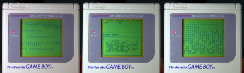
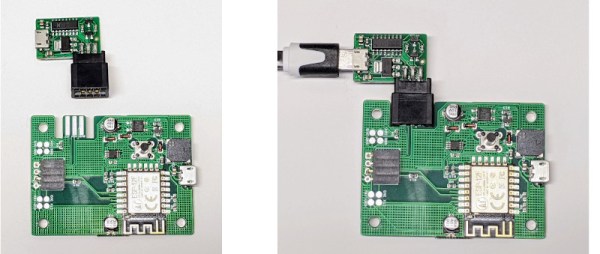
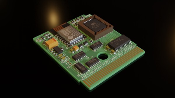
Rather than trying to hook this bus directly to a fast microcontroller, [Staacks] has taken a different approach; by decoding the address bus with discrete logic, it was easy to derive chip selects for an embedded ESP8266 as well as a socketed EEPROM. The clock for the former was also gated and sent into the ESP8266, generating an interrupt to wake it up. The EEPROM stores a simple application whose job is to present an OSD keyboard and send requests to Wikipedia, via the ESP8266 WiFi stack. The resulting text is then displayed on the 160×144 dot matrix display. The interrupt latency of the ESP8266 was mitigated by the application simply discarding the first data byte sent to it, and retrying the access. This way the ESP8266 could spend the majority of its time dealing with wireless duties, only pausing to swap a byte now-and-then with the application. A simple solution which appears to actually work! If you’re up for building one of these and writing your own applications, you can wander over to GitHub, clone yourself a copy and crack on!
We’ve seen a few attempts at doing this before, [davedarko] tried with this project, and if you search hackaday.io you’ll get loads of GB hacks to browse. Finally a recent twitter thread also points to another effort to do something similar with Wi-Fi, but development is still ongoing. We’ll check back later!
Continue reading “ESP8266 Based WiFi Game Boy Cartridge Browses WikiPedia”