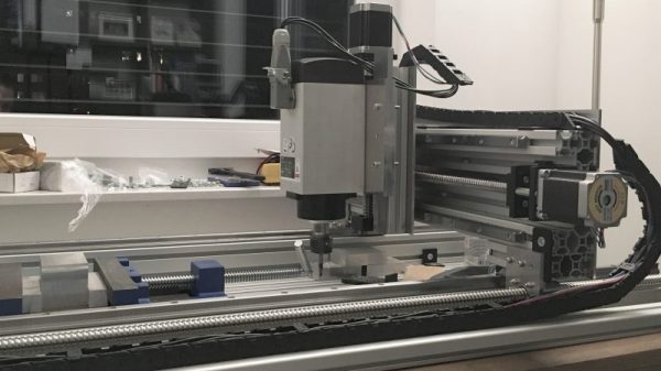
A lot of homebrew CNC machines end up being glorified plotters with a router attached that are good for little more than milling soft materials like wood and plastic. So if you have a burning need to mill harder materials like aluminum and mild steel quickly and quietly, set your sights higher and build a large bed CNC machine with off-the-shelf components.
With a budget of 2000 €, [SörenS7] was not as constrained as a lot of the lower end CNC builds we’ve seen, which almost always rely on 3D-printed parts or even materials sourced from the trash can. And while we certainly applaud every CNC build, this one shows that affordable and easily sourced mechatronics can result in a bolt-up build of considerable capability. [SörenS7]’s BOM for this machine is 100% catalog shopping, from the aluminum extrusion bed and gantry to the linear bearings and recirculating-ball lead screws. The working area is a generous 900 x 400 x 120mm, the steppers are beefy NEMA23s, and the spindle is a 3-kW VFD unit for plenty of power. The video below shows the machine’s impressive performance dry cutting aluminum.
All told, [SörenS7] came in 500 € under budget, which is a tempting price point for a machine this big and capable.
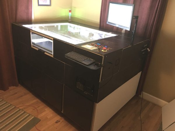
The bachelor in question, [drandolph], rightly points out that a $6,000 build that takes up a significant fraction of the floor space in one’s apartment is better attempted without the benefit of spousal oversight. Still, what spouse couldn’t love the finished product? With a custom aluminum extrusion frame (which barely made the trip from China intact) it’s a sturdy affair, and who could deny the appeal of the soft glow of an LED-illuminated work chamber? A custom exhaust system with sound-deadening, a water chiller for laser cooling, an Arduino-controlled status beacon – there’s even a 3-D printed beer holder on the control panel! And think of all the goodies that will come off the enormous bed of this thing. Note to self: make sure wife sees this post.
There are cheaper and smaller laser cutters, but what’s the point if you have the freedom to go big?
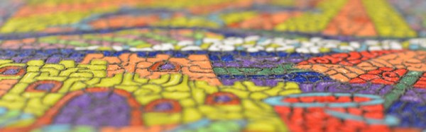
3D printing is obviously best used in printing three-dimensional objects. Laser cutters, jig saws, and CNC routers are obviously well-equipped to machine flat panels with intricate shapes out of plastic sheets, plywood, or metal, but these devices have one drawback: they’re subtractive manufacturing, and 3D printers add material. What good is this? [Jason Preuss] demonstrated a very interesting 3D printing technique at this year’s Midwest RepRap Festival. He’s producing 2D paintings with a 3D printer, with results that look like something between very intricate inlay work and a paint by numbers kit.
[Jason Preuss]’ multicolor 2D print. Notice the toolpaths in the reflection of the upper left hand corner. Click to embiggen.[Jason] is using a 3D printer, a series of very specialized techniques, and a software stack that includes a half-dozen programs to print multicolor 2D scenes. This isn’t pigment, paint, dye, or ink; the artwork becomes a single piece of plastic with individual colors laid down one at a time.
The best example of [Jason]’s work is a copy of a paint by numbers scene. Here, [Jason] makes an outline of all the shapes, separates onto different layers by color, and prints each color, one layer at a time. It’s an incredibly labor-intensive process to even get models into a slicer. Actually printing the model is even more difficult. [Jason]’s paint by numbers scene uses about twelve different colors.
[Jason]’s 3D printed paint by numbers scene. About a dozen different colors were used for this print.We’ve seen [Jason]’s work at MRRF before, including last year’s exhibition of a fantastic chocolate clock that was a 3D printed version of an old scroll saw pattern. Taking what is normally a 2D design and translating that into something that can be built with a 3D printer seems to be [Jason]’s forte, and the results are remarkable. If you don’t know what you were looking at, you would just think these art pieces are a strange industrial fabrication process. Once you look closer, you have an immediate respect for the artistry and craftsmanship that went into a sheet of plastic only a few millimeters thick and no bigger than a piece of paper.
[Jason] hasn’t documented his build process for these 2D pictures on a 3D printer quite yet. There’s a reason for that: it’s supposedly very complicated, and it’s going to take a while to get all the documentation together. Eventually, the process will be documented and a tutorial will pop up on [Jason]’s website. He’s also on Thingiverse, with a few semi-related designs available for download.
From what we’ve seen at MRRF, in the next few years, a dual extrusion printer will be a necessity. While dual extrusion won’t be able to recreate such colorful pictures, it will make the creation of these 2D plastic panels much easier, and they will surely be popular. We can’t wait to see what [Jason] comes up with next.
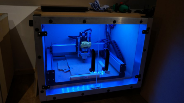
Setting up a desktop CNC brings along two additional problems that need to be resolved – noise and dust. [Nick] upgraded from a Shapeoko2 to the Shapeoko3 and decided to build a fresh dust and noise proof enclosure for his CNC , and it turned out way better than he had anticipated.
When trying to build something like this, aluminium extrusions seem like the obvious choice for the structure. Instead, he opted for low-cost steel frame shelving units. The 3mm thick steel frame results in a nice rigid structure. The top and bottom were lined with 18mm thick MDF panels. For the two sides and back, he choose 60mm noise dampening polyurethane foam lined with 6mm MDF on both sides, and held together with spray adhesive and tight friction fit in the frame.
The frame was a tad shallower and caused the spindle of the Shapeoko3 to stick out the front. To take care of this, he installed an additional aluminium frame to increase the depth of the enclosure. This also gave him a nice front surface on which to mount the 10mm thick polycarbonate doors. The doors have magnetic latches to hold them close, and an intentional gap at the top allows air to enter inside the enclosure. A 3D printed outlet port was fixed to the side wall, where he can attach the vacuum hose for dust collection. The final step was to add a pair of industrial door handles and a bank of blue LED strip lights inside the enclosure for illumination.
It’s a simple build, but well executed and something that is essential to keep the shop clean and dampen noise.
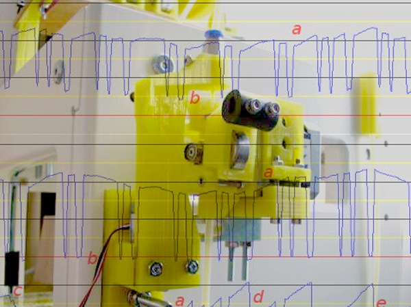
[airtripper] primarily uses a Bowden extruder, and wanted to be a little more scientific in his 3D printing efforts. So he purchased a force sensor off eBay and modified his extruder design to fit it. Once installed he could see exactly how different temperatures, retraction rates, speed, etc. resulted in different forces on the extruder. He used this information to tune his printer just a bit better.
More interesting, [airtripper] used his new sensor to validate the powers of various extruder gears. These are the gears that actually transfer the driving force of the stepper to the filament itself. He tested some of the common drive gears, and proved that the Mk8 gear slipped the least and provided the most constant force. We love to see this kind of science in the 3D printing community — let’s see if someone can replicate his findings.
My printer has other issues that I’m still tuning out, but the warping in PLA and excessive surface roughness has all the signs of over extrusion.
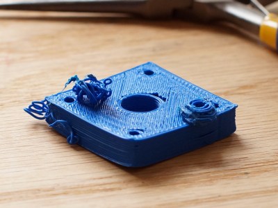
I have an old Prusa i2 that, like an old car, has been getting some major part replacements lately after many many hours of service. Recently both the extruder and the extruder motor died. The extruder died of brass fill filament sintering to the inside of the nozzle (always flush your extruder of exotic filaments). The motor died at the wires of constant flexing. Regardless, I replaced the motors and found myself with an issue; the new motor and hotend (junk motor from the junk bin, and an E3D v6, which is fantastic) worked way better and was pushing out too much filament.
The hotend, driver gear, extruder mechanics, back pressure, motor, and plastic type all work together to set how much plastic you can push through the nozzle at once. Even the speed at which the plastic is going through the nozzle can change how much friction that plastic experiences. Most of these effects are somewhat negligible. The printer does, however, have a sort of baseline steps per mm of plastic you can set.
The goal is to have a steps per mm that is exactly matched to how much plastic the printer pushes out. If you say 10mm, 10mm of filament should be eaten by the extruder. This setting is the “steps per mm” in the firmware configuration. This number should be close to perfect. Once it is, you can tune it by setting the “extrusion multiplier” setting in most slicers when you switch materials, or have environmental differences to compensate for.
This little guy lets you tune the steps per mm exactly.
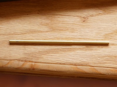
The problem comes in measuring the filament that is extruded. Filament comes off a spool and is pulled through an imprecisely held nozzle in an imprecisely made extruder assembly. On top of all that, the filament twists and curves. This makes it difficult to hold against a ruler or caliper and get a trustworthy measurement.
I have come up with a little measuring device you can make with some brass tubing, sandpaper, a saw (or pipe cutter), a pencil torch, solder, and some calipers. To start with, find two pieces of tubing. The first’s ID must fit closely with the filament size you use. The second tube must allow the inside tubing to slide inside of it closely. A close fit is essential.
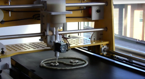
In case you didn’t know it, pancake art is a thing. People are turning out incredible edible artwork using squeeze bottles and pancake batter. But even if you’re not terribly artistic, you can still amaze your breakfast buddies with this robotic pancake printer.
At its simplest – and in our opinion its most impressive – pancake art involves making patterns with thin batter on a hot griddle. The longer the batter is cooked, the darker it becomes, and art happens. To capitalize on this, [Trent], [Kevin], [Sunny] and [Isaac] built a 2-axis gantry with a working area the size of an electric griddle. A bottle is pressurized with a small air pump and controlled by a solenoid valve to serve as a batter extruder, and an Arduino controls everything. Custom pancake design software lets you plan your next masterpiece before committing it to batter.
Sadly, the video below shows us that the team didn’t include an automatic flipper for the pancake, but no matter – that’ll make a great feature for the next version. Maybe something like this?
![[Jason Preuss]' multicolor 2D print. Notice the toolpaths in the reflection. Click to embiggen.](https://hackaday.com/wp-content/uploads/2016/03/p2pchristmastree.jpg)
![[Jason]'s 3D printed paint by numbers scene. About a dozen different colors were used for this print.](https://hackaday.com/wp-content/uploads/2016/03/pppaintbynumber.jpg)