A CNC Plasma Cutter Table, From The Shop Floor Up

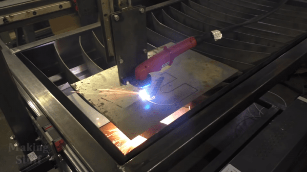
Some projects are simple, some focus on precision and craftsmanship, and some are more of the quick-and-dirty variety. This home-built CNC plasma cutter table seems to follow a “go big or go home” philosophy, and we have to say we’re mighty impressed by the finished product.

For those who follow [Bob]’s “Making Stuff” YouTube channel, this build has been a long time coming. The playlist below has eight videos that cover the entire process from cutting the first tubes of the welded frame to the initial test cuts with the finished machine. [Bob] took great pains to make the frame as square and flat as possible, to the extent of shimming a cross member to correct a 0.030″ misalignment before welding. He used good-quality linear rails for each axis, and hefty NEMA 23 steppers. There were a few false starts, like the water pan that was going to be welded out of five separate pieces of steel until the metal shop guys saved the day with their press brake. In the end, the machine turned out great; with a build cost of $2000 including the plasma cutter it’s not exactly cheap, but it’s quite a bargain compared to similar sized commercial machines.

We think the video series is a great guide for anyone looking to make a CNC plasma table. We’ve seen builds like this before, including [This Old Tony]’s CNC router. Watching these builds gives us the itch to get into the shop and start cutting metal. Continue reading “A CNC Plasma Cutter Table, From The Shop Floor Up”

Wireless Charger Gives A Glimpse Into Industrial Design Process

Almost every product on the market has been through the hands of an industrial designer at some point in its development. From the phone in your pocket to the car in your driveway or the vacuum in your closet, the way things look and work is the result of a careful design process. Taking a look inside that process, like with this wireless phone charger concept, is fascinating and can yield really valuable design insights.

We’ve featured lots of [Eric Strebel]’s work before, mainly for the great fabrication tips and tricks he offers, like how to get a fine painted finish or the many uses of Bondo. But this time around, he walks us through a condensed version of his design process for a wireless phone charger and stand. His client had specific requirements, like being able to have the phone held up in landscape or portrait mode, so he started with pen and paper and sketched some ideas. A swiveling cylinder seemed to fit the bill, and after a quick mockup in PVC pipe, he started work on a full-size prototype in urethane foam. There are some great fabrication tips in the video below, mainly centered on dealing with not owning a lathe.

The thing for us with all of [Eric]’s videos, but especially this one, is seeing the design process laid out, from beginning to (almost) the end. He sure makes industrial design look like a cool gig, one that would appeal to the Jacks- and Jills-of-all-trades who hang out around here.

Continue reading “Wireless Charger Gives A Glimpse Into Industrial Design Process”

When Stirling Engines Meet 3D Printers

Let’s face it, everybody wants to build a Stirling engine. They’re refined, and generally awesome. They’re also a rather involved fabrication project which is why you don’t see a lot of them around.

This doesn’t remove all of the complexity, but by following this example 3D printing a Sterling engine is just about half possible. This one uses 3D printing for the frame, mounting brackets, and flywheel. That wheel gets most of its mass from a set of metal nuts placed around the wheel. This simple proof-of-concept using a candle is shown off in the video after the break, where it also gets an upgrade to an integrated butane flame.

Stirling engines operate on heat, making printed plastic parts a no-go for some aspects of the build. But the non-printed parts in this design are some of the simplest we’ve seen, comprising a glass syringe, a glass cylinder, and silicone tubing to connect them both. The push-pull of the cylinder and syringe are alternating movements caused by heat of air from a candle flame, and natural cooling of the air as it moves away via the tubing.

We’d say this one falls just above mid-way on the excellence scale of these engines (and that’s great considering how approachable it is). On the elite side of things, here’s a 16-cylinder work of art. The other end of the scale may not look as beautiful, but there’s nothing that puts a bigger smile on our faces than clever builds using nothing but junk.

Continue reading “When Stirling Engines Meet 3D Printers”

Hybrid 3D-Printer Creates Complete Circuits, Case And All

The cool kids these days all seem to think we’re on the verge of an AI apocalypse, at least judging by all the virtual ink expended on various theories. But our putative AI overlords will have a hard time taking over the world without being able to build robotic legions to impose their will. That’s why this advance in 3D printing that can incorporate electronic circuits may be a little terrifying, at least to some.

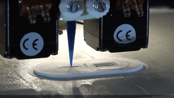
The basic idea that [Florens Wasserfall] and colleagues at the University of Hamburg have come up with is a 3D-printer with a few special modifications. One is a separate extruder than squirts a conductive silver-polymer ink, the other is a simple vacuum tip on the printer extruder for pick and place operations. The bed of the printer also has a tray for storing SMD parts and cameras for the pick-and-place to locate parts and orient them before placing them into the uncured conductive ink traces.

The key to making the hardware work together though is a toolchain that allows circuits to be integrated into the print. It starts with a schematic in Eagle, which joins with the CAD model of the part to be printed in a modified version of Slic3r, the open-source slicing package. Locations for SMD components are defined, traces are routed, and the hybrid printer builds the whole assembly at once. The video below shows it in action, and we’ve got to say it’s pretty slick.

Sure, it’s all academic for now, with simple blinky light circuits and the like. But team this up with something like these PCB motors, and you’ve got the makings of a robotic nightmare. Or not.

Continue reading “Hybrid 3D-Printer Creates Complete Circuits, Case And All”

PCB Production On The Sienci Mill One

A complete start to finish electronics prototyping workshop is nirvana for many of us: being able to go from design on the computer to real hardware without having to get up from your rolling chair. The falling prices of 3D printers have helped make at least part of this a reality: $200 USD is enough to get you a printer that can churn out decent looking enclosures. But there’s more to producing your own hardware than creating slick looking project boxes; at some point you’ll need to put some electronics in there.

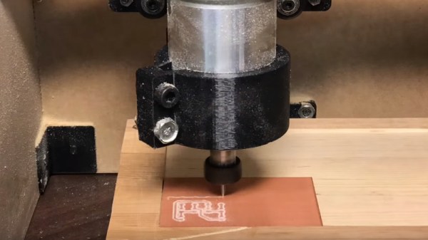
For [Chuck Hellebuyck] at least, the last piece of the puzzle has just fallen into place. He’s recently put up a YouTube video describing how he converted his $399 Sienci Mill One into a capable PCB mill. With a 3D printer and this new PCB mill, he’s happy to say he can now go from concept to production all on the same workbench.

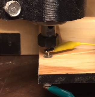
The Sienci Mill One is a solid enough mill in its own right but did need some modification to attain the accuracy necessary for cutting at a depth of only .9 mm. First, a block of wood was cut to the same size as the original plastic bed of the Sienci, and then the mill itself was used to drill holes through the wood block and plastic bed. The wood was attached to the bed using a nut and bolt in each corner, being sure to torque it down enough that the head of the bolt is pulled down flush with the surface of the wood.

Pulling the head of the bolts flush wasn’t just to keep the surface free of any snags, [Chuck] uses them in conjunction with a probe in the mill’s chuck as a simple way of adjusting the Z height. With a continuity meter attached between the two, he could lower the probe down until they were touching just enough to make a circuit.

Click through the break for the rest of the story!

Continue reading “PCB Production On The Sienci Mill One”

Drill The Wet Side Wet And The Dry Side Dry

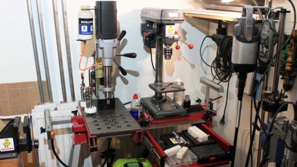
Working mostly in metal as he does, [Tuomas Soikkeli] has invested in some nice tools. So when his sweet magnetic-base drill was in need of a new home, he built this two-in-one drilling station to maximize shop space and add some versatility to boot.

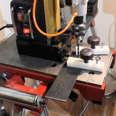
For the non-metalworkers out there, a mag-base drill is basically a portable drill press where the base is replaced with a strong electromagnet like the one shown here. They’re often used in the construction trades to drill holes in steel beams or columns, and often include nice features like a built-in coolant system.

[Tuomas] effectively turned his mag-base drill into a very beefy drill press by mounting it to a disused miter saw stand. A thick piece of plate steel forms the base, and with holes and drain channels machined into it, used coolant can be captured in a drain pan below for reuse. A second base for a benchtop drill press means he’s got a dry drilling station too, and the original support arms on the miter stand are ready for drilling long stock. The drawer below the dry side is a nice touch too.

There’s a lot to learn about fabrication from [Tuomas]’ video and the others on his channel, which is well worth checking out. And if you want to convert your drill press into a mag-base drill, why not check out this microwave oven transformer to electromagnetic crane project for inspiration?

Continue reading “Drill The Wet Side Wet And The Dry Side Dry”

Shop-Made Fixture Turns Out Dream Welds

You can tell a lot about a person by the company they keep, and you can tell a lot about a craftsman by the tools and jigs he or she builds. Whether for one-off jobs or long-term use, these ad hoc tools, like this tubing rotator for a welding shop, help deliver results beyond the ordinary.

What we appreciate about [Delrin]’s tool is not how complex it is — with just a motor from an old satellite dish and a couple of scooter wheels, it’s anything but complicated. What we like is that to fabricate some steering links, each of which required three passes of TIG welding to attach a threaded bung to the end of a rod, [Delrin] took the time to build just the tool for the job. The tools slowly rotates the rod, letting the welder keep the torch in one position as the workpiece moves under it. The grounding method is also simple but clever — just a wide strap of braid draped over the rod. The result is some of the prettiest and most consistent welds we’ve seen in a while, and with an order for 28 steering links, it ought to be a huge time saver.

It may be time for a little more TIG welding love around here. Sure, we’ve covered the basics of oxy-acetylene welding, and even talked about brazing aluminum. Perhaps your humble Hackaday writer will take the plunge into a new TIG welder and report from a newbie’s perspective. You know, for science.

[via r/welding]