We’ll admit it. The closer a project is to completion, the less enthusiasm we have for it. Once the main design is clearly going to work on a breadboard, we’re ready to move on to the next one. We don’t mind the PCB layout, especially with modern tools. However, once the board is done, you have to do the case. Paradoxically, this was easier in the old days because you just picked some stock box, drilled some holes, and while it looked terrible, it was relatively easy.
Today, the bar is much higher. You’ll probably 3D print or laser cut an enclosure. If it looks no better than what you did in the 1970s, you won’t win many admirers. We routinely cover projects that could easily pass for commercial products. So how do you do it?
The Parts
The enclosure may even be the easy part. There are plenty of scripts and generators that will make you a nice box that meets your specifications. You can probably even get the holes made as you build. Back in the day, it was a challenge to cut odd-shaped holes for things like serial port connectors. Now, no problem. The printer or laser will just make a hole with any shape you like. You may even want to try a new angle on 3D printing.
Mounting the PCB isn’t that hard, either. With 3D printing, you can create standoffs, but even if you laser cut, you can easily use conventional standoffs. In a pinch, we’ve used long bolts with nuts.
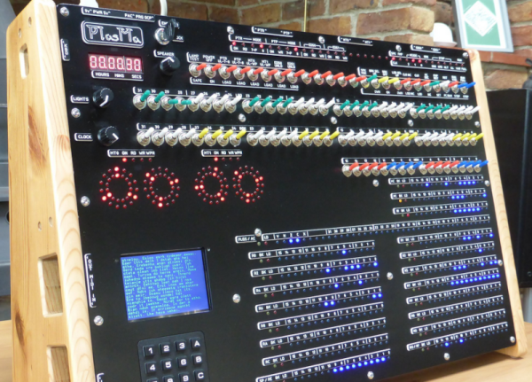
The real problem, it seems to us, is the front panel. Only Star Trek can get away with front panels containing a bunch of knobs and dials with no markings. And although we call them “front” panels, sometimes you need markings on the back or even the sides, too. Continue reading “Ask Hackaday: How Do You Make Front Panels?”