The new Raspberry Pi Zero is generating a lot of discussion, especially along the lines of “why didn’t they include…?” One specific complaint has been that audio is only available through the HDMI port. That’s not entirely true as pointed out by Lady Ada over at Adafruit.
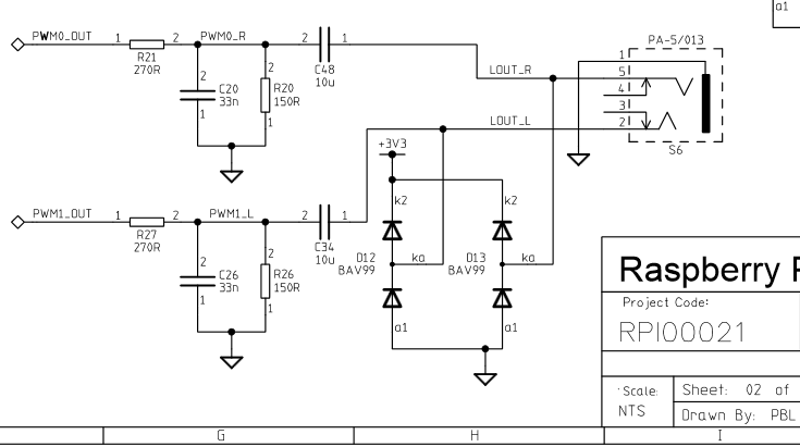
Something to remember about the entire Pi family is the pins on the Broadcom processors are multipurpose. Does it increase the confusion or the capabilities? Take your pick. But the key benefit is that different pins can handle the same purpose. For audio the Greater Than Zero Pis (GTZPi) use PWM0_OUT and PWM1_OUT on the processor’s GPIO pins 40 and 45. On the GRZPis these feed a diode, resistor and capacitor network that ends at the audio output jack. They don’t appear on the GPIO connector so cannot be used on the Zero.
The multi-pin, multi-purpose capability of the Broadcom processor allows you to switch PWM0_OUT to GPIO 18 and PWM1_OUT to GPIO 13 or 19. Add the network from the Adafruit note, or check this schematic from the Raspberry Pi site – look at the lower right on the second page.
While you’re checking out the audio hack at Adafruit, read through the entirety of Introducing the Raspberry Pi Zero. Lady Ada provides a great description of the Zero and what is needed to start using it.
If you’re looking for Zero hacking ideas you might check the comments in our announcement about the Zero or article on the first hack we received. There is a lot of grist for the hacking mill in them.