The first program anyone writes for a microcontroller is the blinking LED which involves toggling a general-purpose input/output (GPIO) on and off. Consequently, the same GPIO can be used to read digital bits as well. A traditional microcontroller like the 8051 is available in DIP packages ranging from 20 pins to 40 pins. Some trade the number of GPIOs for compactness while other devices offer a larger number of GPIOs at the cost of complexity in fitting the part into your design. In this article, we take a quick look at applications that require a larger number of GPIOs and traditional solutions for the problem.
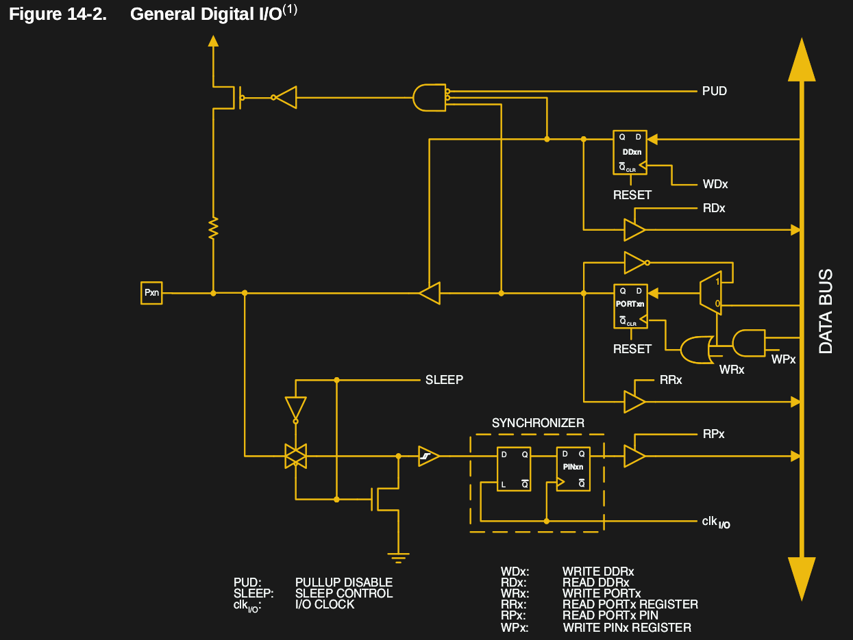 A GPIO is a generic pin on an integrated circuit or computer board whose behavior, including whether it is an input or output pin, is controllable by the user at runtime. See the internal diagram of the GPIO circuit for the ATmega328 for reference.
Simply put, each GPIO has a latch connected to a drive circuit with transistors for the output part and another latch for the input part. In the case of the ATmega328, there is a direction register as well, whereas, in the case of the 8051, the output register serves as the direction register where writing a 1 to it sets it in output mode.
The important thing to note here is that since all the circuits are on the same piece of silicon, the operations are relatively fast. Having all the latches and registers on the same bus means it takes just one instruction to write or read a byte from any GPIO register.
Continue reading “General Purpose I/O: How To Get More”