Taking Halloween To The Next Level With JARVIS

As an avid “Haunt Hacker”, [Steve Koci] knows a thing or two about bringing high-tech to Halloween. Wanting to build a mobile robot that could accompany him to conventions as a demonstration of the sort of animatronic mechanisms and controls he uses, he came up with the idea of JARVIS. The original plan was to make a more traditional robot, but with the addition of an animated skull and some Steampunk-style embellishments, JARVIS is definitely the kind of thing you don’t want to run into on an October night.

Construction of JARVIS started in 2016, after [Steve] saw the Agent 390 tracked robot chassis from ServoCity. With the addition of extra wheels and a custom track, he converted the Agent 390 into a triangular track arrangement which he said he’s had his eye on since “Johnny 5” sported them back in Short Circuit.

There’s a dizzying array of electronics required to make JARVIS move and talk, not least of which is the “Banshee” prop controller. This device is made to simplify the construction of animatronic heads and provides not only organic-looking randomized movement but automatic jaw synchronization. Using a wireless audio connection, [Steve] is able to talk through a speaker mounted on the chest of the robot, while the skull automatically matches its mouth to his speech in real time. Combined with the GoPro in a two-axis gimbal, this allows JARVIS to function as a fairly robust telepresence platform. Much to the delight/horror of those it’s used on.

Getting JARVIS to move requires not only the two beefy motors and a dedicated controller supplied by the Agent 390 platform, but no less than thirteen servos for the head, arms, and grippers. There’s even a linear actuator used to tilt the skull up and down, presumably for terrifying people of various heights and ages. JARVIS even has a pair of Adafruit’s electronic eyes mounted in the skull, as if you thought you would be spared the horror of seeing glowing eyes following you in the dark.

To control all this hardware, [Steve] uses two RC transmitters in conjunction with a smartphone displaying the video feed coming from the GoPro. It takes some serious finger-gymnastics to get JARVIS doing its thing, which [Steve] says he’s still trying to master.

As many projects that have graced these pages can attest to, hackers seem to delight in coming up with new and exciting ways to terrify the young and old alike. Sometimes they can’t even wait until Halloween.

Continue reading “Taking Halloween To The Next Level With JARVIS”

Building A Skyrim Quest Marker

I’m working on a Skyrim quest marker. You probably know what this is even if you never have played the game. When a character or location in the game relates to a quest, an arrow floats over it so you don’t miss it. If it’s a book, the book has the arrow floating over it. If it’s a person, it floats over that character’s head. It is that quest marker I aim to re-create.

I sat down in front of my sketchbook and drew the basic parameters. I wanted it to be approximately to scale to the human/elf/orc heads it usually floats above. I ended up going with around 9 inches from top to bottom. In terms of thickness, any amount of blatant dimensionality is bad, as the game element exists in only 2 dimensions. That said, I will be re-creating this thing in the real world, and LEDs and acrylic and plywood and other things need to go inside.

I decided to make it around 1.25 inches thick, which would include enough space for a 9V battery if I so chose, plus a proto board and microcontroller.

Designing the Electronics

Before I finalized the dimensions I had to design the circuit. Originally I looked at Adafruit’s backlight LED panels, but I felt it would be too hard to fit into the pointy parts of the enclosure, both physically and in terms of light distribution. Instead I went with a strand of cold white LEDs, not individually addressable but only require power and GND to light up. However, the strand is WAY too bright straight from the battery. Fortunately, the strand is PWMable so I am using an Adafruit Trinket ATtiny85 breakout to dim it down somewhat.

I chose a TIP-120 for the switching, a part highly recommended by our own [Adam Fabio]. Power supply will be my wall wart; if I were to take it out into the wild, I could put a 9V battery inside the enclosure — there’s room — but I think I’ll just have it at home this time around.

Designing the Enclosure

I decided to be flexible with my design. I was going use the laser cutter to cut each layer of the marker out of eighth-inch material. The front will have a bezel holding the acrylic in place, while the back is just a blank piece of plywood. The interior layers, of unknown quantity (as I designed it) would determine the overall thickness of the marker.

I opened up Inkscape and went to work designing the layers. I did everything in a single Inkscape file with each layer corresponding with a similar layer on the design.

Closer to lasering, when I have a good sense of the projects’s final parameters, I’ll distribute the layers on a series of 12”x12” Inkscape canvases, and I’ll print directly from these. This will allow me to cut some filler projects in the unused portion of the boards, because I’m cheap like that.

The topmost bezel was easy — it’s supposed to look a specific way. I dropped a GIF from the ‘nets into Inkscape and traced it. I duplicated that layer and made the bottom plate, which is basically just a filled-in version of the bezel. There needed to be the vinyl for the light-emitting part, with some sort of bezel keeping it in place. There also needed to be a board for the LEDs, and beneath the LED board there needed to be room for a small circuit board.

I ended up making the whole thing 10 layers thick: Beginning from the top: the outer bezel; then the acrylic and its carrier, which nestle together — I didn’t want any light escaping from the sides. The third layer is an “under bezel” which lifts the acrylic up 1/8” because the LED strips are covered in a little “hill” of plastic. Fourth, the LED plate, painted white with lengths of LED strip attached to it.

I consider those four layers to be the top of the project. The next six are the bottom, consisting of five identical layers making up the electronics compartment, with the back plate, which also has a hole for the power supply and also mounts the protoboard. Each layer is 1/8″ thick, for an overall thickness of 1.25″ — not too bad. It’s somewhat on the heavy side. (By the way, you can find the Inkscape file in the project page.)

Lasering

The first fifteen minutes of lasering was hell, as I got all the settings figured out. But once I got everything dialed in, it was a breeze.

The layers were split onto 12″x12″ sheets, with two layers per. So I imported 1″x2″ rectangles with horse shapes on them, and you can see them on the right. We use these in my gaming group for horses, with a figure sitting on top of it to show he or she is mounted.

Once I got dialed into my favorite settings, the lasering went quite well. The wood was about one notch lower in terms of quality than what I’m used to, and I felt like the glue was just a little more refractory or whatever. Still, most of the parts came out perfectly.

I was mostly worried about the acrylic. I took a chance with some translucent white acrylic I found on Amazon. Having never used it before, or had a clear understanding (sorry) of how translucent it was, I bought it sight unseen. Furthermore, I had enough real estate on my 12″x12″ sheet for maybe 3 cuts, so I wanted to get the right settings ASAP.

It worked better than I could have hoped. Someone at the hackerspace had written the best ratio of speed and power on the laser cutter room’s whiteboard walls — 15 speed, 8 power. I ran it through twice to be sure, but it came out perfect, and slid into place like a charm.

The Build

I glued the bottom six layers right there in the hackerspace, as well as the two-layer carrier for the acrylic. All I needed to do was paint the thing, add the electronics, and bolt it together.

Originally I’d envisioned a battery pack inside a harness of some sort, with a black-painted PVC pipe hoisting the marker overhead. That seems like a lot to tackle between now during my first run at the project, so I converted the idea to a tabletop version that uses a wall wart.

When I was prototyping the electronics it had occurred to me that I might be a little ridiculous about the Trinket — what if it didn’t need to be PWMed down? Oh, but it does. LED strips run at full brightness are awfully bright, and that cold white that has all the subtlety of a klieg light. They definitely need to be PWMed down.

The strip comes with a 3M adhesive backing, which was great, However, the solder pads that were most accessible were on the underside, as the top is covered in a plastic bubble that is hard to cut away, even with a sharp knife.

For  the future development, I plan to swap in an ESP and use it as a Twitter alert. In addition, the enclosure was hastily designed and lacked a certain polish. For instance, I would like to use trapped nuts on the top three layers to secure the front bezel from behind, so it doesn’t have those intrusive socket heads showing — or at least inset them somehow.

But all in all I’m happy to have the enclosure work out so well the first try. After countless lasered projects with every grade of success from “abject debacle” on up, maybe I’m starting to get a hang of it! Check out the project page on Hackaday.io.

The Internet Of Jack-O’-Lanterns

As the candy rush fades, the Halloween hacks continue pouring in. [Jeremy S Cook] has taken a few fundamental concepts and dressed them up inside the smartest pumpkin on the block.

This pumpkin has a WEMOS D1 Mini ESP8266 brain, LED eyes in place of a candle for illumination, and a small USB power bank for power. The code [Cook] is using is a modified sketch by YouTuber [Innovative Tom], which creates a server on your network — don’t forget to insert your network credentials! — that enable control of the LEDs from your computer or smart phone.

[Cook] has wired the LEDs to the relevant pins on the D1 Mini, zip-tied the battery and board together and stuff them in a plastic bag to keep them dry. Stick that into the pumpkin, hot glue the LEDs in place, and test it out!

Continue reading “The Internet Of Jack-O’-Lanterns”

Pumpkin Piano Promises A Gourd Time

Fall – it’s that time of year that brings falling leaves, Hallowe’en, and a pumpkin version of everything that you hold dear. In this case, it’s not a latte – it’s [Robert Vorthman]’s Pumpkin Piano.

[Robert] took a straightforward approach to the build, pressing a Raspberry Pi into service as the backbone of the operation. This is combined with an Adafruit breakout board for the MPR121, which is a chip that provides 12 capacitive touch-sensitive inputs. These are connected to the bountiful produce which make up the piano keys in this fun holiday hack. [Robert] uses some Python code that talks to fluidsynth, a software synthesizer that uses Soundfont files to create different sounds. It’s all wrapped up with some Neopixels that flash when each vegetable is triggered.

The build would make a great party piece for just about any fall gathering, and [Robert] has done a great job of rolling up all the hardware and software required in the write-up. For another take on a vegetable-based orchestra, check out last year’s Harpsi-gourd.

Scary LEGO chocolate dispensing machine

Mechanical Marvel Trades Courage For Chocolate

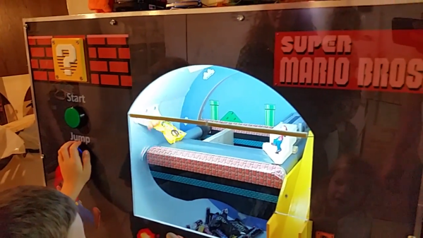
When we see what [Jason Allemann] does with LEGO, we wonder why more one-offs aren’t made this way. This time he’s made a Halloween mechanical marvel that will surely scare more kids than anything else they’ll encounter on their rounds — so much so that many may even decline the chocolate it dispenses. Who wouldn’t when to get it you have to reach over an animatronic skeleton hand that may grab you while a similarly mechanized spider may lunge onto your hand.

The chocolate dispensing, the hand and the spider are all animated using four motors, a LEGO Mindstorms EV3 brick to control them, and a touch sensor. When a kid presses a pumpkin attached to the touch sensor, the next chocolate candy is lowered by gravity onto a conveyor belt and carried forward to the awaiting child. That much is automatic. At the discretion of [Jason] and his partner [Kristal], using an infrared remote control and sensor, they can activate the skeleton hand and the lunging spider at just the right moment. We’re just not sure who they’ll choose to spare. It is Halloween after all, and being scared is part of the fun, so maybe spare no one? Check out the video below and tell us if you’d prefer just the treat, or both the trick and treat.

We do have to wonder if there’s any project that can’t benefit from LEGO products, even if only at the prototype stage or to help visualize an idea. As a small sample, [Jason]’s also made a remote-controlled monowheel and an actual working printer along with a Morse key telegraph machine to send it something to print.

Continue reading “Mechanical Marvel Trades Courage For Chocolate”

This Mask Will Make You A Psycho

Videos games are a cornucopia of project ideas well-suited to the talents of makers and hackers, and Halloween is as good a time as any to show them off! Reddit user [Tavarin], a huge fan of the Boderlands video games, whipped up a plaster mask — replete with glowing eyes — of one of the game’s signature enemies: the Psycho.

[Tavarin]’s secret to forming comfortable plaster masks is to open his jaw while the wrap is setting  — that way he’ll be able to talk without breaking the mask off his face. Hot gluing in and modifying a 60mm PC fan and a pair of lenses meant that the only thing standing between him and a lot of sanding to shape the mask’s details was a few layers of thick plaster mix.

Continue reading “This Mask Will Make You A Psycho”

Haunting A Smart Mirror With Hue And Alexa

So, your smart mirror has been running for a while, but Halloween is coming up and you want to come up with some cool Halloween stuff to display on the mirror. If you’re looking for ideas, check out [Ben Eagan]’s cool Haunted Smart Mirror which connects the mirror via a Raspberry Pi with Amazon Alexa and Phillips Hue lighting.

[Ben] points to another of his blog pages for those readers interested in the nuances of setting up Alexa with a smart mirror, while concentrating on communication with the Hue bridge and creating the setup for a new Alexa command in this post. Dealing with the Phillips Hue API seems fairly straightforward: Get the IP address of your Hue bridge from your router and the ID of your lights from the Hue app and you’re set to send commands via HTTP. [Ben] includes a Python script to make the lights flicker, which you can modify for your own lights as you wish. Once that’s done, you’ll need to set up the intent that Alexa listens for, and then modify the AWS lambda function that sends commands to the Pi. When the command shows up in the queue on the Pi, any commands [Ben] wants to play are fired off – in this case, a video is played and the Hue lights start to flicker.

There’s no mention of security in the article, so that may be worth a little attention with Alexa and the Hue, but with Halloween coming up fast even if you haven’t built a magic mirror yet, if you’ve got Hue lights, this would be a great, quick, Halloween idea. Especially if you could combine it with your outside lights so that Trick-or-Treaters can join in on the fun. Maybe you’d prefer looking up passing planes using Alexa? Or how about getting your fish to talk?

Continue reading “Haunting A Smart Mirror With Hue And Alexa”