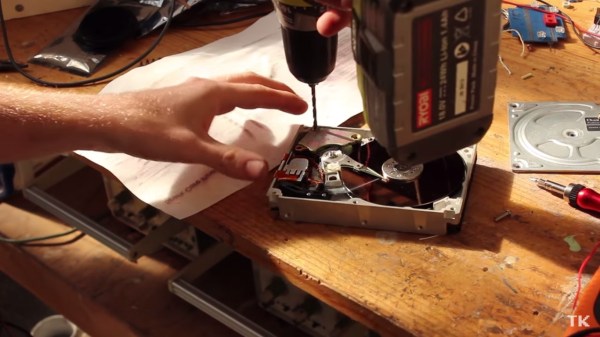
So you’ve just taken apart a hard drive, and you’re looking at all the pieces on your desktop. You’re somehow compelled to use them all in different projects. Why not pull out that very high quality bearing that keeps the platters spinning at high RPMs and build this simple anemometer with it? That’s what [Sergei Bezrukov] did, and it looks like a perfect el cheapo project.
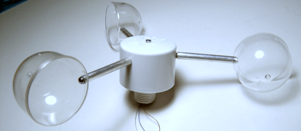
The build is fairly low-tech and entirely sufficient. The cups are made from plastic containers that used to contain pantyhose. A Hall-effect sensor and a magnet take care of measuring the rotations, feeding its signal into a PIC that calculates the wind speed from the revolution rate. The rest of the housing is PVC, with some other miscellaneous parts found at the hardware store.
To calibrate the device, [Sergei] made a second hand-held unit that he could (presumably) drive around in a car to get a baseline wind speed, and then note down the revolution rate. Once you’ve got a good reference, holding the portable unit up to the permanent one transfers the calibration.
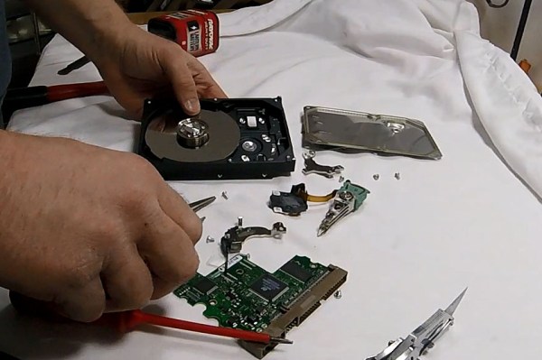
But the star of the show, that lets the anemometer spin effortlessly, is the sweet bearing that used to spin a hard-drive platter. If you haven’t played with one of these bearings before, you absolutely should. We just ran a post on taking apart a hard drive for its spare-parts goodness so you have no excuse. If you’re feeling goofy, you can mount one onto a board, step on it with the ball of your foot, and spin. They’re quality bearings, and you’ll be surprised how quickly you can spin as you pull your arms in.
Thank [Matt] for the tip!
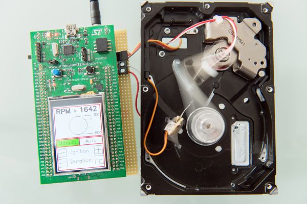
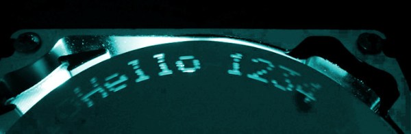
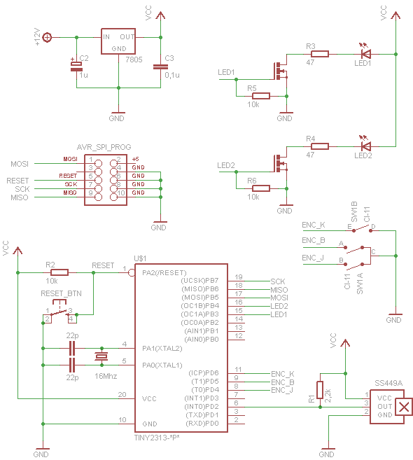 He used the frame, disk and motor from a drive and added LEDs under the spinning disk as the light source. The disk has 8 small holes drilled equidistant around the disk, and spiraling slightly toward the center. As the holes pass by the LEDS they are flashed by the ATtiny2313 processor to create images. To determine the position of the platters a Hall effect sensor is monitored by the 2313 to detect a magnet on the underside of the disk. There is room to display ten characters at one time. Each cursor position can scroll through the character set by rotating an encoder. For all the precision needed to coordinate the LEDs with the spinning holes the electronics and software code are amazingly simple. That’s a really nice job, [Adam]!