Spectrum Analyzer Users Custom Characters On An HD44780 Display

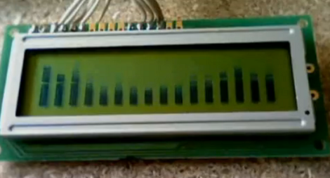
[Camilo] built a spectrum analyzer to use with his audio system (translate). The hardware is quite simple, using an op-amp, microcontroller and LCD display. He chose an LMV324M low-voltage op-amp which connects to the incoming audio signal and feeds its output to the microcontroller’s ADC. In this case, he chose a Freescale microcontroller from the HCS08 family which is running at 20 MHz. This gives the project enough speed to properly analyze the incoming audio. He mentions that he’s following the guidelines set forth in the Nyquist-Shannon sampling theorem and using the Fast Fourier Transform when processing the samples.

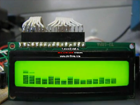
This isn’t the first time we’ve seen a character LCD used as a display for a frequency analyzer. This other ATmega8-based rendition supported several different screen layouts. These displays have enough RAM to store eight custom characters. Each character is 5×8 pixels, lending eight levels to each character for a total of 16 for each column seen above. We love the simplicity of the hardware in the project but we wouldn’t mind seeing an additional potentiometer to fine-tune how the data is displayed on the screen to take advantage of its full range. See the project in action in the clip after the break.

Continue reading “Spectrum Analyzer Users Custom Characters On An HD44780 Display”

Building A Message Board With A Web Interface

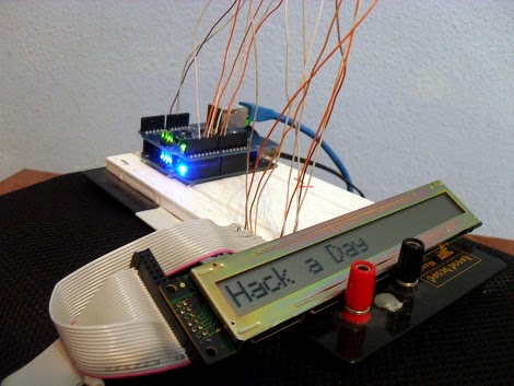
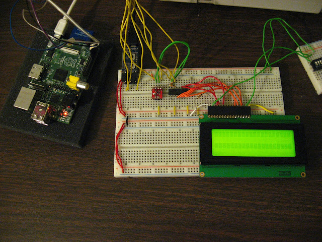
[Sergio] is just getting into hardware hacking. He started by getting an HD44780 compatible LCD screen running with his Arduino. To take the project to the next level, he decided to add a web interface for changing the message displayed on the LCD.

He’s doing things on the cheap (a man after our own hearts), purchasing many of his components off of eBay. Unfortunately that decision came back to bite him when it was time to connect his Arduino to the network. The Ethernet Shield knock-off wasn’t the same as the official version. That one’s got a Wiznet W5100 ethernet chip with does a lot of the heavy lifting for you. Instead, [Sergio] is using a board with an ENC28J60. It took a bit of searching, but eventually he came up with an example to help him get his Arduino serving web pages and listening for updates from them.

The ENC28J60 is actually not a bad piece of hardware. It’s cheap enough, and there are a few hardware/software demos out there that are worth taking a look at.

An Alarm For Every Day Of The Week

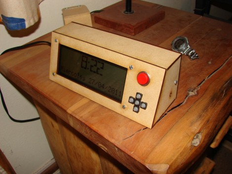
If you don’t have a 9-to-5 type of job you might find yourself constantly resetting your alarm clock as your calendar commitments change. [Lucas] finally got fed up with the nightly ritual and decided to build his own alarm clock which has unique settings for each day of the week (translated).

The display itself is an LM044L 20×4 character display. This provides a viewing area that is about 3″x1″ and since it’s an HD44780 compliant LCD screen, writing data to it takes very little effort (and RAM) compared to a graphic LCD. A PIC 18F2550 drives the device, taking input from a half-dozen buttons, driving the display, and turning on the enclosed buzzer when it’s time to get up. There’s a backup battery which will keep the settings when power is lost. The daily alarms, current time, and back light brightness can all be adjusted from the four screens that make up the settings menus. The only thing that it’s missing is a precision timekeeper, but that should be easy to add either by measuring the frequency of the mains or by using an RTC chip.

Shift Register Is All It Takes To Make A 3-wire Serial LCD

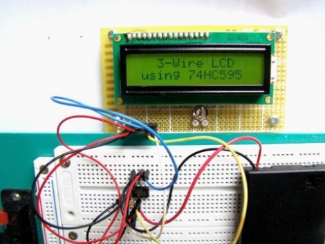
This hack is a bit older, but one aspect of the setup makes it worth sharing. Shift registers are a common component to include in a project when you need to increase the number of I/O pins available. We’ve used them to drive LCD screens before, but we never realize you could use a 595 chip to make a 3-wire serial LCD interface. That’s because we’ve always thought of shift registers as having three control pins which must be addressed: data, clock, and latch. But it seems that’s not the case. This hack gangs the pins for clock and latch (called the storage register clock input on this chip) together. This causes the shifted data to be latched to output register one clock cycle after it is shifted into the chip.

This means you can operate the 595 chip with just two pins, but alas, you do need one more connection to drive the LCD properly. This is an HD44780 compliant display. It is being used in 4-bit mode; four of the shift register pins provide that data, while a fifth controls the Register Select pin. Since the shifted data from the 595 appears on the pins after each clock strobe, you must control the Enable pin on the LCD separately or it will behave sporadically.

So there you have it, control an HD44780 display with just 3-pins by using a $0.42 part. Are we going a little too fast for you? Check out this 595 tutorial and give the shift register simulator a try. That should bring you up to speed.

[Thanks Rajendra]

Full-featured AVR Time-lapse

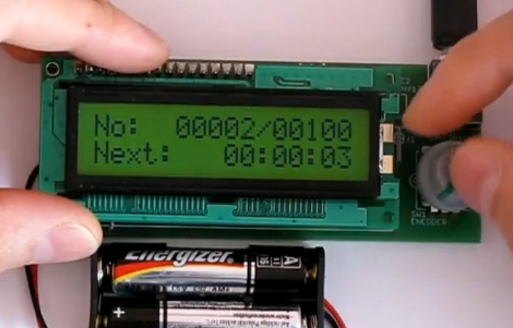
This time-lapse photo trigger was built [Lukasz Goralczyk]. It is controlled by an ATmega168 and we were surprised to read that it uses about 12k of code. Curious about what takes up that much space, we were impressed to see all the features demonstrated in the video after the break. The small device, running on two AA batteries, has a well-designed user interface displayed on a 3V character LCD that is navigated with a clickable rotary encoder.

It isn’t the smallest intervalometer we’ve ever seen, but it deserves respect for the features packed into a diminutive form-factor.

Continue reading “Full-featured AVR Time-lapse”

Portable WiFi Penetration Testing

Inside this box you’ll find a La Fonera wireless access point. [Emeryth] and his band of miscreants built this portable device for WiFi security testing. The AP is running OpenWRT and has been set up to use the 16×4 character display as a terminal. An ATmega88 connects the LCD as well as six buttons to the UART of the La Fonera. From there, a set of Ruby scripts takes care of the communication protocol. As you can see after the break, this setup allows you to scan the area for WiFi, showing channel, SSID, and MAC information. Although not specifically outlined in the video we suspect there’s some more devious tricks up its sleeve too.

Continue reading “Portable WiFi Penetration Testing”

Solder Station Hack Adds Temperature Control

Take that cheap fire stick you call a soldering iron and turn it into a real tool. [Giorgos Lazaridis] turned his 30 watt soldering iron into a temperature controlled soldering station by adding a thermistor just above the tip to monitor how hot things are getting. A MAX6675 takes care of the thermocouple and shoots a digital temperature value off to the PIC 16F88 which controls the unit by taking user input from a potentiometer and displaying the settings on an HD44780 character display. His use of a dissected ‘wall wort’ inside of the ATX power supply carcass used as the case for the station is a clever hack. See it melt some metal in the clip after the break.

This makes a nice upgrade to our solder station guide, which had a temperature controlled iron but lacked the sensor and automation seen here. Continue reading “Solder Station Hack Adds Temperature Control”