Protel Autotrax is a PCB design tool first released for DOS in the mid-80s. Consider this a look at the history of PCB design software. I’m not recommending anyone actually use Protel Autotrax — better tools with better support exist. But it’s important to know where we came from to understand the EDA tools available now. I’m rolling up my sleeves (about 30 years worth of rolling) and building our standardized test PCB with the tool. Beyond this, I suggest viewing EEVblog #747, where [Dave] digs into one of his old project, Borland Pascal, and Protel Autotrax.
This is the continuation of a series of articles demonstrating how to Create A PCB In Everything. In this series, we take a standard reference circuit and PCB layout — a simple ATtiny85 board — and build it with different PCB design tools. We’ve already covered Eagle in this series. We learned Fritzing is a joke for PCB design, although it is quite good for making breadboard graphics of circuits. Each of these tutorials serves as a very quick introduction to a specific PCB design tool. Overall, this series provides for a comparison between different PCB design tools. Let’s dig into Protel Autotrax.
A short history of Protel, Altium, and Autotrax
The company we know as Altium today was, for the first fifteen years of its existence, known as Protel. Back in the day, PCB design on a computer required a dedicated workstation, a lot of hardware, light pens, and everything was extraordinarily expensive. Protel was a reaction to this and the first product, Autotrax, was a DOS-based program that brought PCB design to the PC. A freeware version of Autotrax is still available on the Altium website and can be run from inside a DOS virtual machine or DOSBox.
Interestingly, Protel Autotrax is not the only PCB design software named Autotrax. A company called DEX 2020 has also has a PCB design software called AutoTRAX. This is weird, confusing, and I can’t figure out how this doesn’t violate a trademark. If anyone has any insight to what the Protel / Altium legal department was doing a few decades ago, your wisdom is welcome in the comments.
Sometimes it’s not so much what you put together, it’s how you use it. The folks at Adafruit have put up a project on how to dress up your drone with ‘UFO lights’ just in time for Halloween. The project is a ring of RGB LEDs and a small microcontroller to give any quadcopter a spinning ‘tractor beam light’ effect. A 3D printed fixture handles attachment. If you’re using a DJI Phantom 4 like they are, you can power everything directly from the drone using a short USB cable, which means hardly any wiring work at all, and no permanent changes of any kind to the aircraft. Otherwise, you’re on your own for providing power but that’s probably well within the capabilities of anyone who messes with add-ons to hobby aircraft.
One thing this project demonstrates is how far things have come with regards to accessibility of parts and tools. A 3D printed fixture, an off-the-shelf RGB LED ring, and a drop-in software library for a small microcontroller makes this an afternoon project. The video (embedded below) also demonstrates how some unfamiliar lights and some darkness goes a long way toward turning the otherwise familiar Phantom quadcopter into a literal Unidentified Flying Object.
We’ve all taken apart a small toy and pulled out one of those little can motors. “With this! I can do anything!” we proclaim as we hold it aloft. Ten minutes later, after we’ve made it spin a few times, it goes into the drawer never to be seen again.
It’s all their fault
It always seems like they are in everything but getting them to function usefully in a project is a fool’s errand. What the heck are they for? Where do people learn the black magic needed to make them function? It’s easy enough to pull out the specification sheet for them. Most of them are made by or are made to imitate motors from the Mabuchi Motor Corporation of Japan. That company alone is responsible for over 1.5 billion tiny motors a year.
More than Just the Specs
In the specs, you’ll find things like running speed, voltage, stall current, and stall torque. But they offer anything but a convincing application guide, or a basic set of assumptions an engineer should make before using one. This is by no means a complete list, and a skip over the electrics nearly completely as that aspect of DC motors in unreasonably well documented.
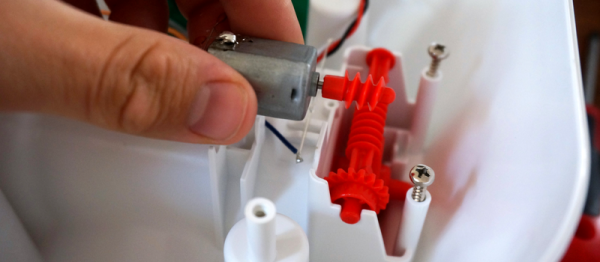
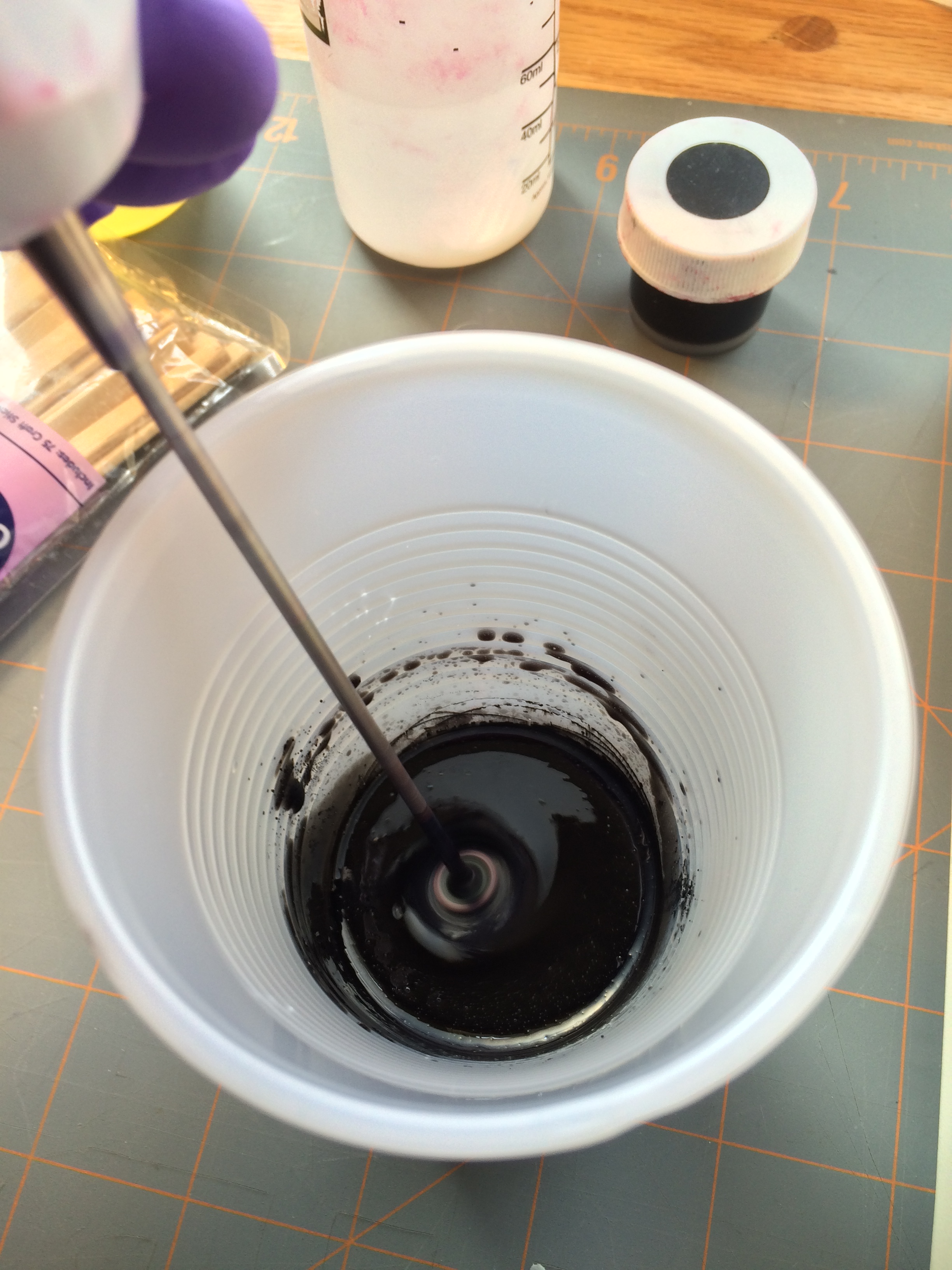
The paint mixers high running speed and infrequent use make it a decent candidate for hooking directly to the motor.
The first thing to note is that they really aren’t meant to drive anything directly. They are meant to be isolated from the actual driving by a gear train. This is for a lot of reasons. The first is that they typically spin very fast, 6,000 – 15,000 rpm is not atypical for even the tiniest motor. So even though the datasheet may throw out something impressive like it being a 3 watt motor, it’s not exactly true. Rather, it’s 3 N*m/s per 15,000 rotations per minute motor. Or a mere 1.2 milliwatt per rotation, which is an odd sort of unit that I’m just using for demonstration, but it gives you the feeling that there’s not a ton of “oomph” available. However, if you start to combine lots of rotations together using a gear train, you can start to get some real power out of it, even with the friction losses.
The only consumer items I can think of that regularly break this rule are very cheap children’s toys, which aren’t designed to last long anyway, and those powered erasers and coffee stirrers. Both of these are taking for granted that their torque needs are low and their speed needs are high, or that the motor burning out is no real loss for the world (at least in the short term).
This is because the motors derate nearly instantly. Most of these motors are hundreds of loops of very thin enameled wire wrapped around some silicon steel plates spot welded or otherwise coerced together. This means that even a small heat event of a few milliseconds could be enough to burn through the 10 micrometer thick coating insulating the coils from each other. Practically speaking, if you stall a little motor a few times in a row you might as well throw it away, because there’s no guessing what its actual performance rating is anymore. Likewise, consistently difficult start-ups, over voltage, over current, and other abuse can quickly ruin the motor. Because the energy it produces is meant to spread over lots of rotations, the motor is simply not designed (nor could it be reasonably built) to produce it all in one dramatic push.
Making Contact
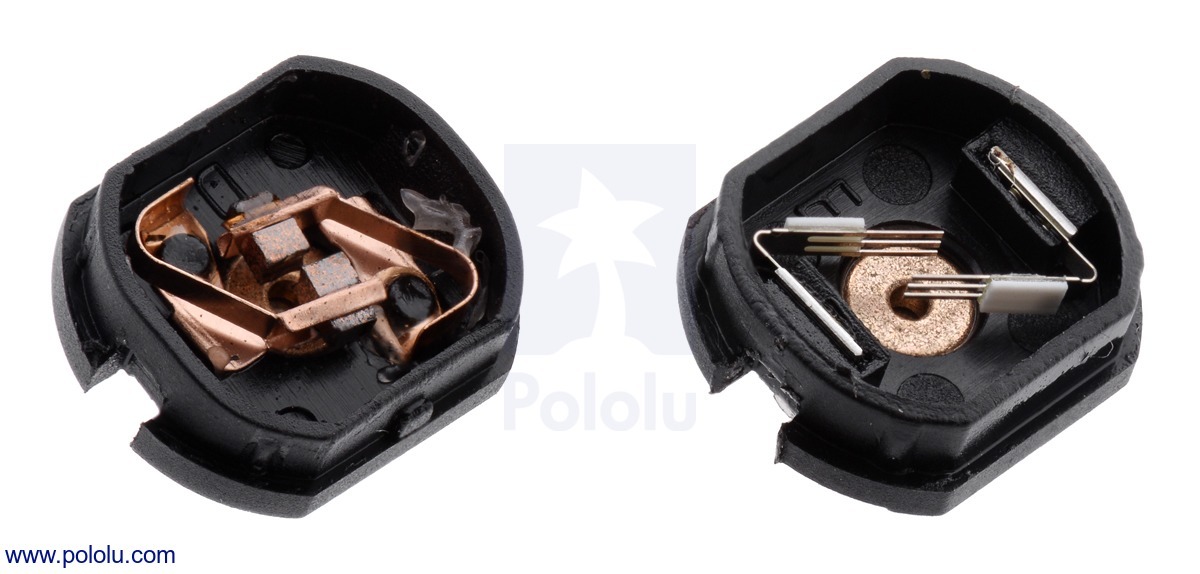
Pololu has the clearest picture of the different kind of brushes inside these small motors.
This brings me to another small note about these tiny motors. Most of them don’t have the carbon brushes one begins to expect from the more powerful motors. Mostly they have a strip of copper that’s been stamped to have a few fingers pressing against the commutator. There’s lots of pros to these metal contacts and it’s not all cost cutting, but unless you have managed to read “Electrical Contacts” by Ragnar Holm and actually understood it, they’re hard to explain. There’s all sorts of magic. For example, just forming the right kind of oxide film on the surface of the commutator is a battle all on its own.
It’s a weird trade off. You can make the motor cheaper with the metal contacts, for one. Metal contacts also have much lower friction than carbon or graphite brushes. They’re quieter, and they also transfer less current, which may seem like a bad thing, but if you have a stalled motor with hairlike strands transferring the pixies around the last thing you’d want to do is transfer as much current as possible through them. However, a paper thin sheet of copper is not going to last very long either.
So it comes down to this, at least as I understand it: if bursts of very fast, low energy, high efficiency motion is all that’s required of the motor over its operational life then the metal strip brushes are perfect. If you need to run the motor for a long stretches at a time and noise isn’t an issue then the carbon brush version will work, just don’t stall it. It will cost a little bit more.
Take Care of Your Tiny Motors
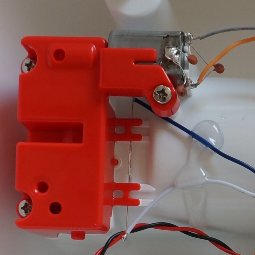
Here is one of these motors being restrained properly. Only torque on the case is restrained. The motor is otherwise free to move.
To touch one other small mechanical consideration. They are not designed to take any axial load at all, or really even any radial load either. Most of them have a plastic or aluminum bronze bushing, press-fit into a simple stamped steel body. So if you design a gearbox for one of these be sure to put as little force as possible on the bearing surfaces. If you’ve ever taken apart a small toy you’ve likely noticed that the motor can slide back and forth a bit in its mounting. This is why.
Lastly, because most of these motors are just not intended to run anywhere near their written maximum specifications it is best to assume that their specifications are a well intentioned but complete lie. Most designs work with the bottom 25% of the max number written on the spreadsheet. Running the motor anywhere near the top is usually guaranteed to brick it over time.
These are useful and ubiquitous motors, but unlike their more powerful cousins they have their own set of challenges to work with. However, considering you can buy them by the pound for cheaper than candy, there’s a good reason to get familiar with them.
This week, we’re continuing our Creating A PCB In Everything series, where we go through the steps to create a simple, barebones PCB in different EDA suites. We’re done with Eagle, and now it’s time to move onto Fritzing.
Fritzing came out of the Interaction Design Lab at the University of Applied Sciences of Potsdam in 2007 as a project initiated by Professor Reto Wettach, André Knörig and Zach Eveland. It is frequently compared to Processing, Wiring, or Arduino in that it provides an easy way for artists, creatives, or ‘makers’ to dip their toes into the waters of PCB design.
I feel it is necessary to contextualize Fritzing in the space of ‘maker movement’, DIY electronics, and the last decade of Hackaday. Simply by virtue of being an editor for Hackaday, I have seen thousands of homebrew PCBs, and tens of thousands of amateur and hobbyist electronics projects. Despite what the Fritzing’s Wikipedia talk page claims, Fritzing is an important piece of software. The story of the ‘maker movement’ – however ill-defined that phrase is – cannot be told without mentioning Fritzing. It was the inspiration for CircuitLab, and the Fritzing influence can easily be seen in Autodesk’s 123D Circuits.
Just because a piece of software is important doesn’t mean it’s good. I am, perhaps, the world’s leading expert at assessing poorly designed and just plain shitty PCBs. You may scoff at this, but think about it: simply due to my vocation, I look at a lot of PCBs made by amateurs. EE professors, TAs, or Chris Gammell might beat me on volume, but they’re only looking at boards made by students using one tool. I see amateur boards built in every tool, and without exception, the worst are always designed in Fritzing. It should be unacceptable that I can even tell they’re designed in Fritzing.
Fritzing has its place, and that place is building graphical representations for breadboard circuits. Fritzing has no other equal in this respect, and for this purpose, it’s an excellent tool. You can also make a PCB in Fritzing, and here things aren’t as great. I want to do Fritzing for this Creating A PCB In Everything series only to demonstrate how bad PCB design can be.
For the next few thousand words, I am going to combine a tutorial for Fritzing with a review of Fritzing. Fritzing is an important piece of software, if only for being a great way to create graphics of breadboard circuits. As a PCB design tool, it’s lacking; creating parts from scratch is far too hard, and there’s no way to get around the grid snap tool. No one should ever be forced to create a PCB in Fritzing, but it does have its own very limited place.
Meetings can actually be useful. It’s hard to believe, but they can actually save time if done right. While most of us are in a perpetual state of torture by Kevin in marketing holding another three-hour meeting during lunch hours, there are a few of us who know their hidden power when put in the right hands.
Working as a contractor, wasted meetings mean wasted billable hours. Even wasted meeting time is covered in the cost of the contract it runs the risk of giving the client the impression that you’re not as productive as originally thought. Organized, productive meetings show that you know what you’re doing and that the cost of your services as a whole is a good value. Yeah, some meetings suck but they are necessary and should be productive.
A meeting needs three things to be worth the time spent on it.
A well prepared for, simple, and clear agenda.
A time limit.
Something needs to be written down at the end of it.
I’ll start with the third item as it shapes the rest. The point of a meeting is to have something to write down at the end of the meeting. Any meeting that ends up in anything requiring fallible human memory was a waste of everyone’s time. This includes, verbal agreements, handshake agreements, ideating (pronounced idioting), brainstorming, think tanking, and the like.
For the next post in the Creating A PCB series, we’re going to continue our explorations of Eagle. In Part 1, I went over how to create a part from scratch in Eagle. In Part 2, we used this part to create the small example board from the Introduction.
This time around I’ll be going over Design Rule Check (DRC) — or making sure your board house can actually fabricate what you’ve designed. I’ll also be covering the creation of Gerber files (so you can get the PCB fabbed anywhere you want), and putting real art into the silkscreen and soldermask layers of your boards.
The idea behind this series is to explore different EDA suites and PCB design tools by designing the same circuit in each. You can check out the rest of the posts in this series right here.
In the last (and first) post in this series, we took a look at Eagle. Specifically, we learned how to create a custom part in Eagle. Our goal isn’t just to make our own parts in Eagle, we want to make schematics, boards, and eventually solder a few PCBs.
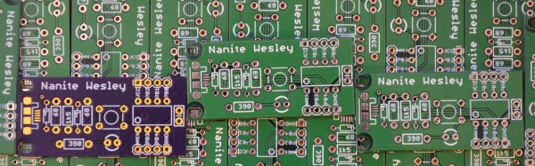
The board we’ll be making, like all of the boards made in this Creating A PCB In Everything series, is the Nanite Wesley, a small USB development platform based on the ATtiny85. This board has less than a dozen parts, most of which are through-hole. This is the simplest PCB I can imagine that has sufficient complexity to demonstrate how to make a board.
With that said, let’s get onto the second part of our Eagle tutorial and lay out our circuit board.