Mike Szczys Ends 8-Bit Vs 32-Bit Holy War!

If you’ve read through the comments on Hackaday, you’ve doubtless felt the fires of one of our classic flame-wars. Any project done with a 32-bit chip could have been done on something smaller and cheaper, if only the developer weren’t so lazy. And any project that’s squeezes the last cycles of performance out of an 8-bit processor could have been done faster and more appropriately with a 32-bit chip.

bits_argument

Of course, the reality for any given project is between these two comic-book extremes. There’s a range of capabilities in both camps. (And of course, there are 16-bit chips…) The 32-bit chips tend to have richer peripherals and run at higher speeds — anything you can do with an 8-bitter can be done with its fancier cousin. Conversely, comparatively few microcontroller applications outgrow even the cheapest 8-bitters out there. So, which to choose, and when?

Eight Bits are Great Bits

The case that [Mike] makes for an 8-bit microcontroller is that it’s masterable because it’s a limited playground. It’s a lot easier to get through the whole toolchain because it’s a lot shorter. In terms of debugging, there’s (often) a lot less that can go wrong, letting you learn the easy debugging lessons first before moving on to the truly devilish. You can understand the hardware peripherals because they’re limited.

And then there’s the datasheets. The datasheet for a chip like the Atmel ATMega168 is not something you’d want to print out, at around 660 pages long. But it’s complete. [Mike] contrasts with the STM32F405 which has a datasheet that’s only 200 pages long, but that’s just going over the functions in principle. To actually get down to the registers, you need to look at the programming manual, which is 1,731 pages long. (And that doesn’t even cover the various support libraries that you might want to use, which add even more to the documentation burden.) The point is, simpler is simpler. And if you’re getting started, simpler is better.

Continue reading “Mike Szczys Ends 8-Bit Vs 32-Bit Holy War!”

Local Hacker Discovers Card Edge Connectors

When [turingbirds] was looking around for the absolute minimum connector for a JTAG adapter, he wanted something small, that didn’t require expensive adapters, and that could easily and reliably connect a few JTAG pins to a programmer. This, unsurprisingly, is a problem that’s been solved many times over, but that doesn’t mean there isn’t room for improvement. [turingbirds] found his better solution by looking at some old card edge connectors.

Instead of 0.1″ pitch pin headers, weirder and more expensive connectors, the Tag Connect, or even pogo pins, [turingbirds] came up with a JTAG adapter that required no additional parts, had a small footprint, and could be constructed out of trash usually found behind any busy hackerspace or garage. The connector is based on the venerable PCI connector, chopped up with a Dremel and soldered to a JTAG or ISP programmer.

This is simply a card edge connector, something the younglings seem to have forgotten. Back in the day, card edge connectors were a great way to connect peripherals, ports, and anything else to the outside world. They were keyed, and you could only put them in one way. They were relatively cheap, and with a big coil of ribbon cable, you could make custom adapters easily. For low-speed connections that will only be used a few times, it’s very hard to beat a card edge connector.

Of course the connector itself is only half of the actual build. To turn a chopped up PCI connector into a JTAG adapter, [turingbirds] made footprint and part files for his favorite PCB design tool. In this case it’s Eagle, and the libraries that will plop one of these connectors down are available on GitHub.

Is this the latest and greatest way to plug a programmer into a board? No, because this has been around for 30 or 40 years. It does, however, put a programming port on a PCB with zero dollars in components, a minimum of board footprint, and uses parts that can be salvaged from any pile of old computers.

An MSP430 Flash Emulation Tool From An MSP430

It isn’t much trouble programming one of TI’s MSP430 chips, but outside of the official Flash Emulation Tool, TI doesn’t make programming one of these microcontrollers cheap. The most common way of programming an MSP430 is using a Launchpad Dev board, and [Vicente] has the best looking one yet.

The MSP430 series of chips can be programmed through JTAG or Spy-By-Wire, and the official, professional engineering tool from TI for these chips costs about $100. Those of us with more sense than money have another option – use one of the TI Launchpad dev boards as an MSP430 programmer.

[Vicente]’s project uses the MSP430G2 Launchpad, with just a few wires going to the proper connector found in the official programmer from TI. There are a few limitations; the programmer only works at 3.6V, so programming 1.8V devices might not be a good idea. Also, it only works with Spy-By-Wire and no JTAG support is available. Still, it’s a great looking project, and does exactly what it’s designed to.


Stepping Through Code On A Pace 4000 Set Top Box

[Lee] wrote in to tell us about a Set Top Box he hacked. Before the cable industry lawyers get out their flaming swords… he’s not stealing cable, or really doing much of anything. This is a hack just for the adventure and thrill of making someone else’s hardware design do your bidding without any kind of instructions.

He posted about the adventure in two parts. The first is finding the JTAG header and identifying the pins. Arduino to the rescue! No really, and this is the type of Arduino use we love. Using a package called JTAGenum the board becomes a quick tool for probing and identifying JTAG connections.

The image above shows a different piece of hardware. From looking at it we’re pretty sure this is a Bus Blaster which is specifically designed for JTAG debugging with ARM processors. This is the beginning of the second part of his documentation which involves code dumping and stepping through lines code (or instructions) using OpenOCD and GDB. It’s a chore to follow all that [Lee] discovered just to write his name to the display of the box. But we certainly found it interesting. The display has a convoluted addressing scheme. We assume that there are cascading shift registers driving the segments and that’s why it behaves the way it does. Take a look for yourself and let us know what you think in the comments.

Unbricking A Router With A Raspi

About a decade ago, [Mansour] learned of the Linksys WRT54G, a wireless router that’s been shoved into just about every project under the sun. After learning of this device’s power, he decided a firmware upgrade was in order. Unfortunately, he accidentally bricked this router and left it sitting on a shelf for a few years.

Idle devices are the devil’s playthings, and when [Mansour] discovered a Samsung hard drive with a an SDRAM that was compatible with the WRT54G, he decided he would have a go at repairing this ancient router. There was only one problem: the most popular utility for programming the router through the JTAG header required a PC parallel port.

No problem, then, as [Mansour] had a Raspberry Pi on hand. The parallel port utility bit-banged the new firmware over to the router, something the GPIO port on the Pi could do in spades. By adding Pi support to the debricking utility, [Mansour] had a functional WRT54G with just a little bit of patience and a few wires connecting the GPIO and JTAG header.

JTAGulator Finds Debug Interfaces

jtagulator

[Joe Grand] has come up with a tool which we think will be useful to anyone trying to hack a physical device: The JTAGulator. We touched on the JTAGulator briefly during our DEF CON coverage, but it really deserves a more in-depth feature. The JTAGulator is a way to discover On Chip Debug (OCD) interfaces on unfamiliar hardware.

Open any cell phone, router, or just about any moderately complex device today, and you’ll find test points. Quite often at least a few of these test points are the common JTAG / IEEE 1149.1 interface.

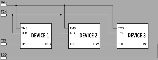
JTAG interfaces have 5 basic pins: TDI (Test Data In), TDO (Test Data Out), TCK (Test Clock), and TMS (Test Mode Select), /TRST (Test Reset) (optional).

If you’re looking at a PCB with many test points, which ones are the JTAG pins? Also which test points are which signals? Sometimes the PCB manufacturer will give clues on the silk screen. Other times you’re on your own. [Joe] designed the JTAGulator to help find these pins.

Continue reading “JTAGulator Finds Debug Interfaces”

Learn JTAG By Writing A Bit-banging Programmer

j-tag-flow-chart

[Pesco] won one of Dangerous Prototypes’ PCB giveaways a few months ago. He opted for a CPLD breakout board. He just needed to put in a parts order and populate the components himself. But then what? He needed a JTAG programmer to work with the chip. Like any good autodidact he choose to make his own rather than buying one. He absorbed the JTAG specification and coded a bit banging programmer using an Arduino.

We’ve used JTAG many times to program ARM chips. But until now we never took the time to figure out how the specification works. If you’ve got an IEEE subscription you can download the whitepaper, but [Pesco] was also able to find one floating around on the interwebs. The flow chart on the left is the cheat sheet he put together based on his readings. From there he wrote the Arduino sketch which implements the programming standard, allowing him to interact with a chip through a minicom terminal window.

[via Dangerous Prototypes]