JTAGulator Finds Debug Interfaces

jtagulator

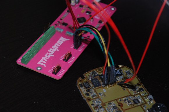
[Joe Grand] has come up with a tool which we think will be useful to anyone trying to hack a physical device: The JTAGulator. We touched on the JTAGulator briefly during our DEF CON coverage, but it really deserves a more in-depth feature. The JTAGulator is a way to discover On Chip Debug (OCD) interfaces on unfamiliar hardware.

Open any cell phone, router, or just about any moderately complex device today, and you’ll find test points. Quite often at least a few of these test points are the common JTAG / IEEE 1149.1 interface.

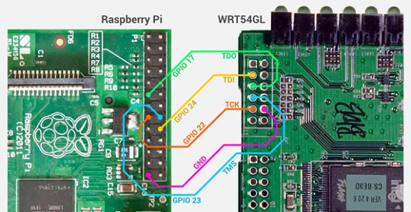
JTAG interfaces have 5 basic pins: TDI (Test Data In), TDO (Test Data Out), TCK (Test Clock), and TMS (Test Mode Select), /TRST (Test Reset) (optional).

If you’re looking at a PCB with many test points, which ones are the JTAG pins? Also which test points are which signals? Sometimes the PCB manufacturer will give clues on the silk screen. Other times you’re on your own. [Joe] designed the JTAGulator to help find these pins.

Continue reading “JTAGulator Finds Debug Interfaces”

Learn JTAG By Writing A Bit-banging Programmer

j-tag-flow-chart

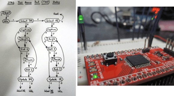
[Pesco] won one of Dangerous Prototypes’ PCB giveaways a few months ago. He opted for a CPLD breakout board. He just needed to put in a parts order and populate the components himself. But then what? He needed a JTAG programmer to work with the chip. Like any good autodidact he choose to make his own rather than buying one. He absorbed the JTAG specification and coded a bit banging programmer using an Arduino.

We’ve used JTAG many times to program ARM chips. But until now we never took the time to figure out how the specification works. If you’ve got an IEEE subscription you can download the whitepaper, but [Pesco] was also able to find one floating around on the interwebs. The flow chart on the left is the cheat sheet he put together based on his readings. From there he wrote the Arduino sketch which implements the programming standard, allowing him to interact with a chip through a minicom terminal window.

[via Dangerous Prototypes]

Evalbot As A JTAG Programmer

evalbot-as-jtag-programmer

[Adarsh] needed a JTAG programmer to push code to a CPLD dev board he was working with. He knew he didn’t have a dedicated programmer but figured he could come up with something. Pictured above is his hack to use a Stellaris Evalbot as a programmer.

Long time readers will remember the Evalbot coupon code debacle of 2010. The kits were being offered with a $125 discount as part of a conference. We were tipped off about the code not know its restrictions, and the rest is history. We figure there’s a number of readers who have one collecting dust (except for people like [Adam] that used it as a webserver). Here’s your chance to pull it out again and have some fun.

A bit of soldering to test points on the board is all it takes. The connections are made on the J4 footprint which is an unpopulated ICDI header. On the software side [Adarsh] used OpenOCD with stock configuration and board files (specifics in his writeup) to connect to the white CPLD board using JTAG.

[Sprite_TM] OHM2013 Talk: Hacking Hard Drive Controller Chips

Even if he hadn’t done any firmware hacking on this hard drive [Sprite_TM’s] digital exploration of the controller is fascinating. He gave a talk at this year’s Observe, Hack, Make (OHM2013) — a non-commercial community run event in the Netherlands and we can’t wait for the video. But all the information on how he hacked into the three-core controller chip is included in his write up.

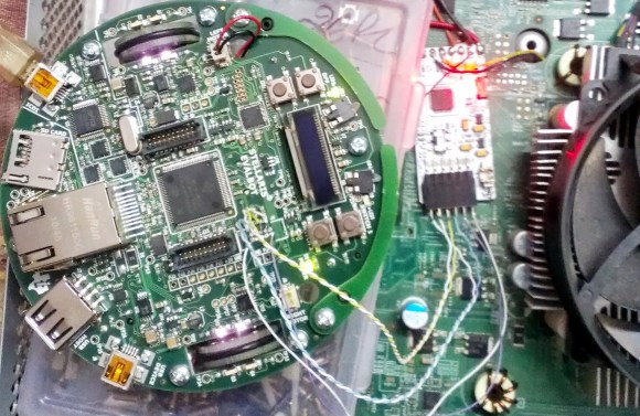
[Sprite_TM] mentions that you’re not going to find datasheets for the controllers on these drives. He got his foot in the door after finding a JTAG pinout mentioned on a forum post. The image above shows his JTAG hardware which he’s controlling with OpenOCD. This led him to discover that there are three cores inside the controller, each used for a different purpose. The difference between [Sprite_TM’s] work and that of mere mortals is that he has a knack for drawing surprisingly accurate conclusions from meager clues. To see what we mean check out the memory map for the second core which he posted on page 3 of his article.

Using JTAG he was able to inject a jump into the code (along with a filler word to keep the checksum valid) and run his own code. To begin the firmware hacking portion of the project he pulled the flash ROM off of the board and installed it on that little board sticking out on the left. This made it easy for him to backup and reflash the chip. Eventually this let him pull off the same proof of concept as a firmware-only hack (no JTAG necessary). He goes onto detail how an attacker who has root access could flash hacked firmware which compromises data without any indication to they system admin or user. But we also like his suggestion that you should try this out on your broken hard drives to see if you can reuse the controllers for embedded projects. That idea is a ton a fun!

When we were poking around the OHM2013 website (linked above) we noticed that the tickets are sold out; good for them! But if you were still able to buy them they take Bitcoin as one payment option. Are there any other conferences that allow Bitcoin for registration?

Etch Your Own CPLD Development Board

etch-your-own-cpld-breakout

Ever wanted to make the jump from microcontrollers to logic chips? Although not technically the same thing we consider FPGA and CPLD devices to be in similar categories. Like FPGAs, Complex Programmable Logic Devices let you build hardware inside of a chip. And if you’ve got the knack for etching circuit boards you can now build your own CPLD development module. Long-time Hackaday readers will remember our own offering in this area.

Our years of microcontroller experience have taught us a mantra: if it doesn’t work it’s a hardware problem. We have a knack for wasting hours trying to figure out why our code doesn’t work. The majority of the time it’s a hardware issue. And this is why you might not want to design your own dev tools when just starting out. But one thing this guide has going for it is incremental testing. After etching and inspecting the board, it is populated in stages. There is test code available for each stage that will help verify that the hardware is working as expected.

The CPLD is programmed using that 10-pin header. If you don’t have a programmer you can build your own that uses a parallel port. Included on the board is an ATtiny2313 which is a nice touch as it can simulate all kinds of different hardware to test with your VHDL code. There is also a row of LEDs, a set of DIP switches, and a few breakout headers to boot.

Serial Port JTAG Programmer

If you’re planning to do some hacking with CPLD or FPGA chips you’ll need a way to program them. JTAG is one of the options and here’s a cheap method that uses the serial port (translated).

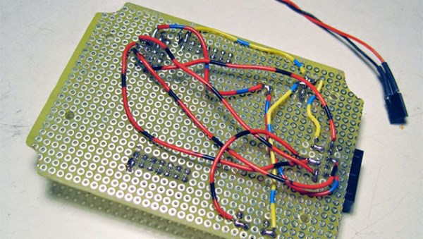
This method requires only four signals (TDI, TMS, TCK and TDO) plus ground. But the problem is that an RS232 serial port operates with 12V logic levels and the JTAG side of the programmer needs to operate with the logic levels native to the device you’re programming. Commercial programmers use a level convert IC to take care of this for you, but that doesn’t mesh with the cheap goal of this project. Instead, [Nicholas] uses Zener diodes and voltage dividers to make the conversion. There is also an LED for each data signal to give some feedback if you’re having trouble.

You can use this along with a programming application that [Nicholas] whipped up using Visual Studio. It works well via the serial port, but he did try programming with a USB-to-Serial dongle. He found that this method slows the process down to an unbearable 5-minutes. Take a look, maybe you can help to get that sloth-like programming up to a manageable speed.

[Thanks Alex]