The MOS 7600 Video Game Chip Gives Up Its Secrets

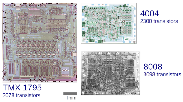
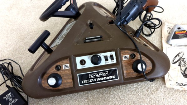
A good chip decapping and reverse engineering is always going to capture our interest, and when it comes from [Ken Shirriff] we know it’s going to be a particularly good one. This time he’s directed his attention to the MOS 7600 all-in-one video game chip (Nitter), a mostly forgotten device from the 6502 chipmaker which we featured a few weeks ago when it was the subject of a blogger’s curiosity. The question then was whether it contained a microprocessor or not and even whether it was another 6502 variant, and the answer revealed in the decapping answers that but will disappoint the 6502 camp.

On the chip is a mixture of analog and digital circuitry, with some elements of a more traditional game chip alongside a ROM, a PLA, and a serial CPU core. The PLA stores pixel data while the ROM stores the CPU code, and the CPU serves to perform calculations necessary to the games themselves. He hasn’t fully reverse-engineered either, but the two areas of the chip are mask-programmed to produce the different games with which the chip could be found.

So the answer to the original question is that there is a CPU on board, but it’s not a 6502 and the operation is a hybrid between dedicated game chip and CPU-controlled chip. What we find interesting is that this serial CPU core might have as we mused in the previous piece made the heart of a usable 1970s microcontroller, was this a missed opportunity on the part of MOS? We’ll never know, but at least another piece of early video game history has been uncovered.

Can You Hear Me Now? Lunar Edition

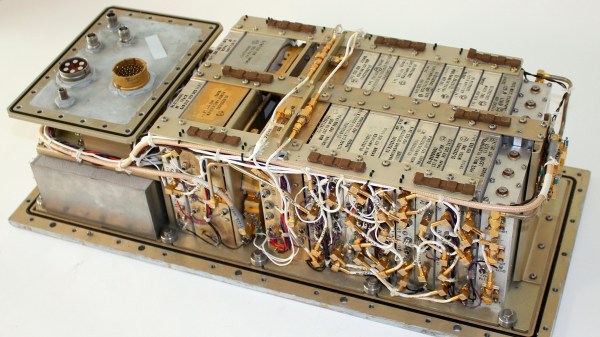
Despite what it looks like in the movies, it is hard to communicate with astronauts from Earth. There are delays, and space vehicles don’t usually have a lot of excess power. Plus everything is moving and Doppler shifting and Faraday rotating. Even today, it is tricky. But how did Apollo manage to send back TV, telemetry, and voice back in 1969? [Ken Shirriff] and friends tell us part of the story in a recent post where he looks at the Apollo premodulation processor.

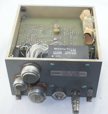
Things like weight and volume are always at a premium in a spacecraft, as is power. When you look at pictures of this solid box that weighs over 14 pounds, you’ll be amazed at how much is crammed into a relatively tiny spot. Remember, if this box was flying in 1969 it had to be built much earlier so there’s no way to expect dense ICs and modern packaging. There’s not even a printed circuit board. The components are attached to metal pegs in a point-to-point fashion. The whole thing lived near the bottom of the Command Module’s lower equipment bay.

Continue reading “Can You Hear Me Now? Lunar Edition”

The Apollo Digital Ranging System: More Than Meets The Eye

If you haven’t seen [Ken Shirriff]’s teardowns and reverse engineering expeditions, then you’re in for a treat. His explanation and demonstration of the Apollo digital ranging system is a fascinating read, even if vintage computing and engineering aren’t part of your normal fare.

The average Hackaday reader should be familiar with the concept of determining the distance of a faraway object by measuring how long it takes a sound or radio wave to be reflected, such as in sonar and radar. Going another step and measuring Doppler Shift – the difference in the returned signal’s frequency – will tell us the velocity of the object relative to our position. It’s so simple that an Arduino can do it. But in the days of Apollo, there was no Arduino. In fact, there were no Integrated Circuits. And Apollo missions went all the way to the moon- far too distant for relatively simple Radar measurements. Continue reading “The Apollo Digital Ranging System: More Than Meets The Eye”

[Ken Shirriff] Takes A Bite Of The Apple-I

The Apple-I was a far cry from Apple’s later products. A $666 single-board computer, the product had some unique design features including using a shift register for video memory to save money. The shift registers of the day required high-current clock pulses that ranged from -11 to 5V and there was a DS0025 clock driver chip to handle the job. [Ken Shirriff] takes the unusual chip apart for us in a recent blog post.

The use of a shift register as memory isn’t a new idea. Really old computers like EDSAC used mercury delay lines as memory which was essentially a physical shift register. In those cases, the ALU and other processing only had to deal with a bit at a time, further simplifying things. For the Apple, there were seven shift registers to store 6-bits of display data and a cursor position. The 6 bits of character data drove — indirectly — a character generator ROM to convert the data into dots for the display.

Driving all those shift register flip flops requires a lot of clock current, so the DS0025 uses an unusual transistor design. There are 24 separate emitters in two groups. It acts like a large transistor, but you could also consider it as two 12-emitter transistors or 24 separate transistors in parallel. The metal wiring, interestingly enough, tapers because at the start of the conductor, the current for all 12 sub-transistors flows, but by the end, it is only the current for the last sub-transistor, so the conductor doesn’t have to be as wide. In addition, the two transistors have to have matched resistance which requires careful design so the transistors turn on at the same time.

The final result is an inverter that can provide 1.5 amps. This current helps overcome the relatively large capacitance in the shift register’s clock line. The clock rate was 1 MHz and the load capacitance was about 150 picofarads.

We enjoy [Ken’s] posts ranging from mysteries to space hardware. It is always interesting to see what is inside these devices or, at least, what was in the old devices we’ve all seen.

A Particularly Festive Chip Decapping

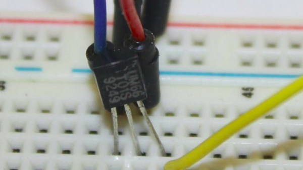
As we approach the moment in the year at which websites enter a festive silly season of scrambling to find any story with a festive angle, we’re pleased to see the ever-reliable [Ken Shirriff] has brought his own take on Christmas tech to the table with a decapping of the UM66T melody chip that has graced so many musical greeting cards.

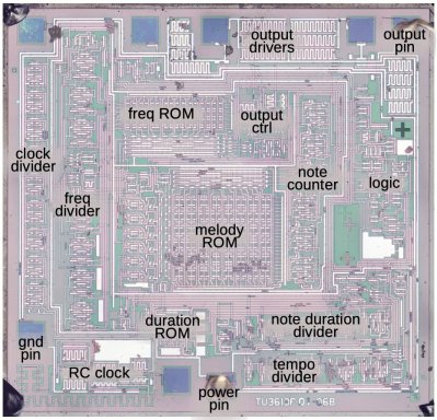
The surprise in this age of ubiquitous microcontrollers is that this is not a smart device; instead it’s a single-purpose logic chip whose purpose is to step through a small ROM containing note values and durations, driving a frequency generator to produce the notes themselves. The frequency generator isn’t the divider chain from the RC oscillator that we might expect, instead it’s a shift register arrangement which saves on the transistor count.
Although the UM66 is a three-pin device, there are a few other pins on the die. These are likely to be for testing. As a 30+ year old product its design may be outdated in 2021, but it’s one of those chips that has survived without being superseded because it does its task without the need for improvement. So when you open a card and hear the tinny tones of a piezo speaker this holiday season, spare a thought for the ingenuity of the design behind the chip that makes it all possible.

Apollo Shift Register Is Discrete

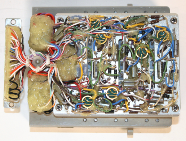
We’re unabashed fans of [Ken Shirriff] here at Hackaday, and his latest post about an Apollo-era transistorized shift register doesn’t disappoint. Of course, nowadays a 16-bit shift register is nothing special. But in 1965, this piece of Apollo test hardware weighed five pounds and likely cost at least one engineer’s salary in the day, if not more.

The incredible complexity of the the Apollo spacecraft required NASA to develop a sophisticated digital system that would allow remote operators to execute tests and examine results from control rooms miles away from the launch pad.

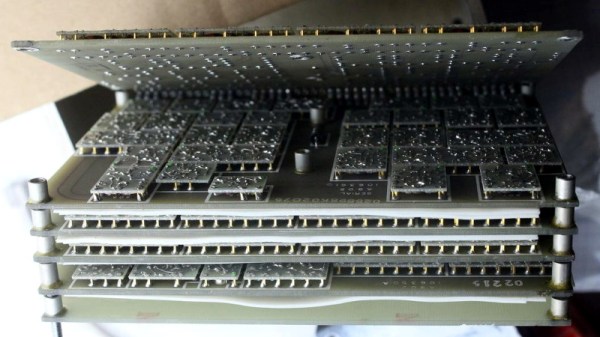
This “Computer Buffer Unit” was used to hold commands for the main computer since a remote operator could not use the DSKY to enter commands directly. Externally the box looks like a piece of military hardware, and on the inside has six circuit boards stacked like the pages of a book. To combat Florida’s notoriously damp conditions, the enclosure included a desiccant bag and a way to fill the device with nitrogen. A humidity indicator warned when it was time to change the bag.

There is a lot more in the post, so if you are interested in unusual construction techniques that were probably the precursor to integrated circuits, diode transistor logic, or just think old space hardware is cool, you’ll enjoy a peek inside this unusual piece of gear. Be sure to check out some of [Ken]’s previous examinations, from tiny circuits to big computers.

[Ken Shirriff] Picks Apart Mystery Chip From Twitter Photo

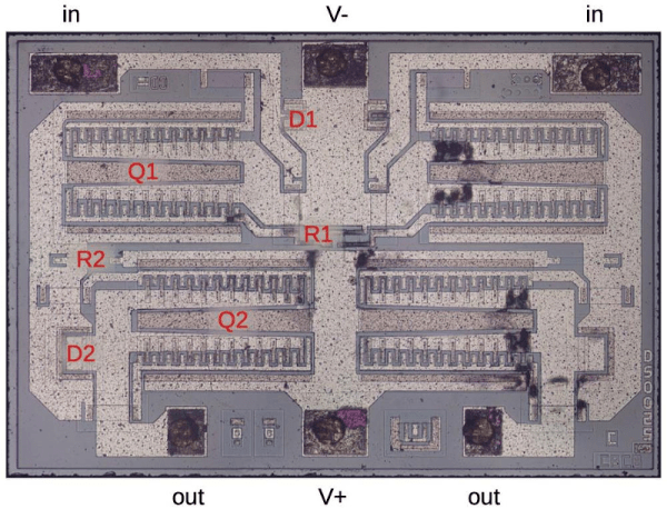
It’s no secret that the work of [Ken Shirriff] graces the front pages of Hackaday quite frequently. He’s back again, this time reverse engineering a comparator chip from a photo on Twitter. The mysterious chip was decapped, photographed under a microscope, and subsequently posted on the internet with an open call to figure out what it did.

[Ken] stepped up, and at first glance, it was obvious that most of the chip is unused, and there appeared to be four copies of the same circuit. After identifying resistors and the different transistor types, [Ken] found differential pairs.

Differential pairs form the heart of most op-amps, and by chaining them together, you can get a strong enough signal to treat it as a logic signal. Based on the design and materials, [Ken] estimates the chip is from the 1970s. Given that it appears to be ECL (Emitter-Coupled Logic), it could just be four comparators. But there are still a few things that don’t add up as two comparators have additional inverted outputs. Searching the part number offered few if any clues, so this will remain somewhat a mystery.

We’ve covered [Ken’s] incredible chip sleuthing before here, such as the Sharp EL-8 from 1969.