Laser-Cut Clock Uses Planetary Gear

[wyojustin] was trying to think of projects he could do that would take advantage of some of the fabrication tech that’s become available to the average hobbyist. Even though he doesn’t have any particular interest in clocks, [wyojustin] discovered that he could learn a lot about the tools he has access to by building a clock.

[wyojustin] first made a clock based off of a design by [Brian Wagner] that we featured a while back. The clock uses an idler wheel to move the hour ring so it doesn’t need a separate hour hand. After he built his first design, [wyojustin] realized he could add a planetary gear that could move an hour hand as well. After a bit of trial and error with gear ratios, he landed on a design that worked.

The clock’s movement is a stepper motor that’s driven by an Arduino. Although [wyojustin] isn’t too happy with the appearance of his electronics, the drive setup seems to work pretty well. Check out [wyojustin]’s site to see the other clock builds he’s done (including a version with a second hand), and you can peruse all of his design files on GitHub.

Looking for more clock-building inspiration? Check out some other awesome clock builds we’ve featured before.

Balancing A Ball With A Solar Cell

Go to any control systems class, and you’ll see a final project that demonstrates loops, integration, and everything else that can be learned in a semester or two of control theory. This project is not from one of those classes. It is, however, very cool: it balances a 40mm steel ball on the rim of a lasercut wood wheel using nothing more than a solar cell as a sensor.

[Manuel] was inspired to build this ball-balancing device after seeing a similar project at CCC about six years ago. He doesn’t remember who made it, and eschewed the PC/Matlab architecture of the original, but this build retains one interesting feature of its muse. The input to the control system is just a high intensity light bulb and a solar cell. The 40mm steel ball blocks the light reaching the solar cell most of the time. Slight variations in voltage go through the control system to keep this ball balanced on top of the wheel.

The only hardware for this build is a motor, a motor driver, and an ATMega644P. The first revision of the hardware was just a few breakout boards stuffed into a rat’s nest of wiring in the base of the build, but this has been fixed in version two with a new PCB. Video below.

Continue reading “Balancing A Ball With A Solar Cell”

Home Theater, Tribute To A Friend

The Greg Williams Theater

Ever since purchasing this house, [Ed] Always wanted a to turn his living room into a home theater, but not just any old projector and a white wall would do. He wanted the whole experience. [Ed] Started with a slightly damaged 12′ wide 4:3 roll up projector screen, he removed the damaged bottom portion and built a static frame to support the now 16:9 screen. Before he could mount the screen, he needed to drywall over a window that was inconveniently located. With the screen now in place, [Ed] framed out the elevated seating platform and steps with some 2×12 topped off with plywood. Next, the carpet that was sitting directly below the platform and steps was removed and then secured on top. Down firing LED fixtures were installed in the steps, to give them that movie theater look and feel. To provide the image, a refurbished HD projector acquired from the Bay of Electronics, was installed in the loft above the living room.

With the theater functional, [Ed] turned his attention to theater decorations. Dimmable ambiance lighting fixtures, using laser cut acrylic and CNC routed starboard (a marine-grade polymer), were made to resemble a film strip. Next a coffee table was crafted out of an equipment road case filled with movie props. Studio logos were painted on the sides with the use of laser cut stencils, and with a glass top, gives the illusion it came off the set of a hollywood movie. The addition of a rebuilt movie poster marquee, movie posters, candy stand, pop corn machine, and with the existing soda fountain and the arcade in the loft, the home theater was almost complete.

In a fitting tribute, [Ed] designed and built a marquee sign to dedicate and name the theater after his cousin Greg, one of his closest friends and avid movie watcher, who had sadly passed away. Video overview of all the hard work after the break.

Continue reading “Home Theater, Tribute To A Friend”

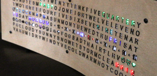
A Laser Cut Word Clock

DIY laser cut word clock.

What is a word clock? A word clock is a clock that displays the time typographically that is also an interactive piece of art. Rather than buy one for $1500, [Buckeyeguy89] decided to build one as a present for his older brother. A very nice present indeed!

There are many different things that come into play when designing a word clock. The front panel is made from a laser cut piece of birch using the service from Ponoko. Additionally, white translucent pieces of acrylic were needed to keep each word’s light from bleeding into the neighboring letters. The hardware uses two Arduinos to control the LEDs and a DS3231 RTC for keeping accurate time. The results are very impressive, but it would sure make assembly easier if a custom PCB was used in the final version. For a one-off project, this makes a great birthday present.

The craftsmanship of this word clock is great, making it well suited for any home. What projects have you built that involve more than just electronics? Sometimes, quality aesthetics make all the difference.

Roboceratops: A Robot Dinosaur That Defies Extinction

roboceratopsInspired by a childhood love of dinosaurs, [Robert] set out to build a robotic dinosaur from the Ceratopsian family. After about a year of design, building, and coding, he has sent us a video of Roboceratops moving around gracefully, chomping a rope, and smoothly wagging his tail.

Roboceratops is made from laser-cut MDF and aluminium bars in the legs. That’s not cookie dough on those legs, it’s upholstery foam, and we love the way [Robert] has shaped it. Roboceratops has servos in his jaw, neck, tail, and legs for a total of 14-DOF. You can see the servo specifics and more in the video description. [Robert] has full kinematic control of him through a custom controller and is working to achieve total quadrupedal locomotion.

Inside that custom controller is an Arduino Mega 2560, an LCD, and two 3-axis analog joysticks that control translation, height, yaw, pitch, and jaw articulation. For now, Roboceratops receives power and serial control through a tether, but [Robert] plans to add an on-board µC for autonomous movement as well as wireless, a battery, an IMU, and perhaps some pressure/contact detection in his feet.

The cherry on top of this build is the matching, latching custom carry case that has drawers to hold the controller, power supply, cable, tools, and spare parts. Check out Roboceratops after the break.

Continue reading “Roboceratops: A Robot Dinosaur That Defies Extinction”

A Huge, Lightweight Wooden Quadrotor

quad_1

[Robert] once built a quadcopter frame by sawing laminate floor tile. It worked, we’re taking the lack of pictures of this build as evidence of how ugly it was. His latest design used a much better looking material – laser cut plywood – and the finished product is very strong and lightweight, even compared to commercial frames made with glass or carbon fiber and epoxy.

Although the design went smoothly thanks to some Solidworks skills, actually cutting the frame from 3mm birch ply resulted in a few issues. The cheap laser cutter used for cutting include some bottom of the line software called LaserWorksV5. There is a kerf compensation feature, called ‘sew compensation’ in the software’s native Chinglish. The software would always crash whenever it tried to calculate the compensation for circles. [Robert] spent two hours figuring this problem out, and in the end needed to break out a piece of sand paper to get a nice interlocking fit.

The completed frame bolts together without any glue at all, and the best part about it is the weight – only 167 grams. Compare that to a similarly sized glass fiber frame, and [Robert]’s shaved at least 200 grams off his finished build.

Vibe Mirror

FLRGC76HP7M9BLI.LARGE

We love a good art-related project here at Hackaday, and [Wolfgang’s] vibrating mirror prototype is worth a look: into its distorting, reflective surface, of course.

[Wolfgang] began by laser cutting nine 1″ circles from an 8″ square mirror, then super glued a 1/4″ neoprene sheet to the back of the square, covering the holes. Each circular cutout received some custom acrylic backings, glued in place with a short piece of piano wire sticking out of the center. The resulting assemblage pushes through the neoprene backing like a giant thumbtack, thus holding all nine circular mirrors in place without restricting movement. The back end of the piano wire connects to yet another piece of acrylic, which is glued to a tiny vibrating motor.

He uses some shift registers and an Arduino Uno to control the motors, and although there’s no source code to glance it, we’re guessing [Wolfgang] simply designed the nine mirrors to buzz about in different patterns and create visually interesting compositions. Check out a quick video of the final effect after the break, and if you can help [Wolfgang] out with a name for his device, hit us up with your suggestions in the comments.

Continue reading “Vibe Mirror”