[Brain] wanted to mark some scissors with his Ortur laser engraver. The problem? The laser won’t cut into the hard metal of the scissors. His solution? Smear the scissors with mustard. No kidding. We’ve heard of this before, and apparently, you can use vinegar, as well, but since the mustard is a paste it is easier to apply. You can see the result in the video, below.
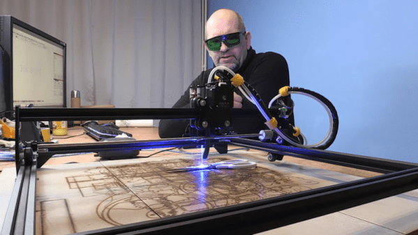
In case you think you don’t need to watch because we’ve already told you the trick, you should know that [Brian] also goes into a lot of detail about preparing single line fonts to get a good result, among a few other tips like improvements to his air assist setup. On a laser cutter, the air assist blows away charred material leaving a clear field of view between the laser and the remaining uncut material. Using a proper air assist can really expand the capabilities of these inexpensive laser cutters — something we recently saw upgraded with a 3D-printed air assist nozzle.
You can buy a commercial marking solution called CerMark Black, but you probably already have mustard. If you are super cheap, you can probably pick up a packet next time you buy a burger somewhere. After all, you don’t need much. Although the video talks about the Ortur, this technique would work with any engraver. We’ve also heard you can do something similar with plaster and alcohol.
Continue reading “Laser Etching Stainless Steel With Mustard”