A MiniDisc Optical Head Has A Few Surprises Up Its Sleeve

There was an odd era at the start of the 1990s when CDs had taken the lead from vinyl in pre-recorded music, but for consumer recordable formats the analogue cassette was still king. A variety of digital formats came to market to address this, of which Sony’s MiniDisc was the only one to gain significant traction outside the studio. These floppy-disk-like cartridges held a magneto-optical medium , and were the last word in cool until being swept away around the end of the decade by MP3 players. Hackaday alum [Nava Whitford] has disassembled a MiniDisc optical head to document how the physical part of the system worked.

The first surprise is that the MiniDisc was in fact a two-in-one system. The recordable discs were magneto-optical and wrote data by heating the disc with a laser under a magnetic field, while the pre-recorded discs used etched pits and lands in a similar way to the CD. Remembering the technical buzz around the system back in the day, either we audio enthusiasts glossed over this detail, or more likely, Sony’s PR did so to emphasize the all-new aspect of the system.

The teardown goes in depth into how while like a CD player there is a photodiode array involved, the extra components are a diffraction grating and a Wollaston prism, an optical component which splits polarized light into two beams. The photodiode array is more complex than that of a CD player, it’s speculated that this is to detect the different polarized beams as well as for the task of maintaining alignment with the track.

All in all this is a rare chance to look at something we know, but which few of us will probably have dismantled due to its relative scarcity compared to CD mechanisms. Definitely worth a look. Meanwhile if this era is of interest, take a look at a Hack Chat we did a while back looking at the MiniDisc’s would-be competitor.

Old Printer Becomes Direct Laser Lithography Machine

What does it take to make your own integrated circuits at home? It’s a question that relatively few intrepid hackers have tried to answer, and the answer is usually something along the lines of “a lot of second-hand equipment.” But it doesn’t all have to be cast-offs from a semiconductor fab, as [Zachary Tong] shows us with his homebrew direct laser lithography setup.

Most of us are familiar with masked photolithography thanks to the age-old process of making PCBs using photoresist — a copper-clad board is treated with a photopolymer, a mask containing the traces to be etched is applied, and the board is exposed to UV light, which selectively hardens the resist layer before etching. [Zach] explores a variation on that theme — maskless photolithography — as well as scaling it down considerably with this rig. An optical bench focuses and directs a UV laser into a galvanometer that was salvaged from an old laser printer. The galvo controls the position of the collimated laser beam very precisely before focusing it on a microscope that greatly narrows its field. The laser dances over the surface of a silicon wafer covered with photoresist, where it etches away the resist, making the silicon ready for etching and further processing.

Being made as it is from salvaged components, aluminum extrusion, and 3D-printed parts, [Zach]’s setup is far from optimal. But he was able to get some pretty impressive results, with features down to 7 microns. There’s plenty of room for optimization, of course, including better galvanometers and a less ad hoc optical setup, but we’re keen to see where this goes. [Zach] says one of his goals is homebrew microelectromechanical systems (MEMS), so we’re looking forward to that.

Continue reading “Old Printer Becomes Direct Laser Lithography Machine”

triggered spark gap

Spark Plug And Plumbing Parts Bring Nitrogen Laser Under Control

When it comes to high-speed, high-voltage switching, there are a wealth of components to choose from — MOSFETS, thyristors, IGBTs, and even vacuum tubes like thyratrons. But who needs all that expensive silicon (or glass) when all you need to build a high-voltage switch is some plumbing fixtures and a lathe?

At least that’s the approach that budget-minded laser experimenter [Les Wright] took with his latest triggered spark gap build. We’ve been watching his work for a while now, especially his transversely excited atmospheric (TEA) lasers. These are conceptually simple lasers that seem easy to build, at least compared to other lasers. But they do require a rapid pulse of high voltage across their long parallel electrodes to lase, and controlling the pulse is where this triggered spark gap shines.

The spark gap is made from brass plumbing fittings on either end of a short PVC coupler. [Les] used his lathe to put a thread into one of the caps to accept a spark plug, the center electrode of which pokes through a small hole in the metal cathode. To trigger the spark gap, [Les] built a trigger generator that outputs about 15,000 volts, which arcs from the spark plug electrode to the spark gap cathode in the low-pressure nitrogen environment. Little spark leads to big spark, big spark discharges a capacitor across the laser electrodes, and you’ve got a controlled single-shot laser. Check it out in the video below.

Honestly, the more we see of [Les]’ videos, the more we want to play with lasers and high voltage. From DIY doorknob caps to blasting Bayer arrays off cheap CCD cameras, there’s always something fun — and slightly dangerous — going on in [Les]’s lab.

Continue reading “Spark Plug And Plumbing Parts Bring Nitrogen Laser Under Control”

The inside of a Laser-Induced Breakdown Spectrometer

Spectrometer Detects Chemicals By Zapping Samples With A Laser Beam

Here at Hackaday, we love projects that result in useful lab equipment for a fraction of the cost of professional gear. [Lorenz], over at Advanced Tinkering, built his own instrument for Laser-Induced Breakdown Spectroscopy, or LIBS, and it’s quite an impressive device. LIBS is a technique for analyzing substances to find their chemical composition. Basically, the idea is to zap a sample with a powerful laser, then look at the little cloud of plasma that results and measure the wavelengths emitted by it.

A plot showing the spectrum of hematite
The spectrum of hematite (iron oxide), compared to that of pure iron

The laser [Lorenz] used is a Nd:YAG unit salvaged from a tattoo removal machine. After it fires a pulse, a photodiode detects the light and triggers a spectrometer, which consists of a diffraction grating, a few lenses and mirrors, and a linear CCD sensor. The grating splits the incoming lights into its constituent components, which fall onto the CCD and trigger its pixels. An STM32 Nucleo board reads out the results and sends them to a PC for further processing.

That processing bit turned out to be a full project on its own. [Lorenz] called upon [g3gg0], who software that simplifies the operation of the spectrometer. First, it helps with the instrument’s calibration. Point the detector at a well-known light source like a laser or a fluorescent lamp, then select the expected wavelengths on the resulting spectral plot. The software then automatically calculates the correct coefficients to map each pixel to a specific wavelength.

The software also contains a database of spectra corresponding to chemical elements: once you’ve taken a spectrum of an unknown sample, you can overlay these onto the resulting plot and try to find a match. The resulting system seems to work quite well. Samples of iron oxide and silver oxide gave a reasonable match to their constituent components.

We’ve seen other types of spectrometers before: if you simply want to characterize a light source, check out this Raspberry Pi-based model. If you’re interested in chemical analysis you might also want to look at this open-source Raman spectrometer.

Continue reading “Spectrometer Detects Chemicals By Zapping Samples With A Laser Beam”

High-Power Laser Salvaged From Headlights

[DiodeGoneWild]’s latest video lives up to the name. He takes apart a laser headlight to recover a pretty powerful blue laser. You can see the video, below.

The headlights work with blue laser diodes that excite phosphor to produce white light. Removing the outside trappings revealed a three-pin laser diode (the case is the third pin). There’s also a substantial heatsink. Removing the diode from the assembly is difficult, but it is easy enough to leave it in the heatsink and use the existing connector.

Of course, the phosphor and a filter have to go. Some destructive work with a screwdriver and pliers broke out the optics from a diode he’d destroyed trying to remove it. Then he replaced the optics on the remaining diode with the modified housing.

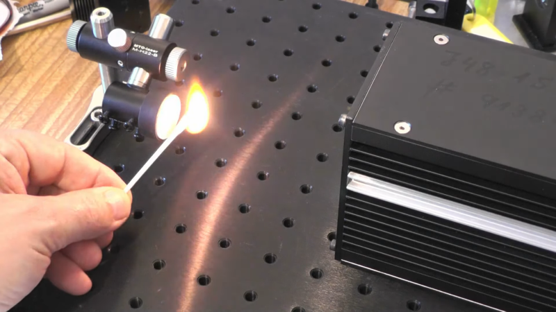
With a low-current test, the diode didn’t lase but did act as a regular LED. More current did the trick, though. The laser without the optics made a line rather than a spot but still had enough power to melt some plastic and light matches. To get a parallel beam, the internal lens needs to move closer to the diode, and a drill bit allowed that to happen, which reduced the beam’s divergence quite a bit, but didn’t create the best result.

With the proliferation of cheap laser modules, it is really worth scrapping a headlight? Maybe. But it is an interesting look inside of a modern headlight, either way. We’ve peeked inside these headlights before. Maybe you can turn those old headlights into an oven.

Continue reading “High-Power Laser Salvaged From Headlights”

As Fast As A Speeding Bullet

[Electronoobs] built a coil gun and the obvious question is: how fast is the projectile? To answer it, he built a chronograph suitable for timing a bullet. The principle is straightforward. A laser and a light sensor would mark the entry and exit of the projectile over a known distance. As it turns out, there are some issues to resolve.

For one thing, a laser is too narrow and might miss the projectile. The first attempt to rectify this used mirrors, but the loss was too great — we suspect he was using a second surface mirror. The final answer was to use an array of detectors and removed the laser’s collimation lens to cover a wider area.

Continue reading “As Fast As A Speeding Bullet”

Integrating sphere test setup

Cannonball Mold Makes A Dandy Integrating Sphere For Laser Measurements

It’s an age-old riddle: if you have a perfect sphere with a perfectly reflective inner surface, will light bounce around inside it forever? The answer is pretty obvious when you think it through, but that doesn’t mean that you can’t put the principle to use, as we see with this homemade Ulbricht sphere for optical measurements.

If you’ve never heard of an Ulbricht sphere, don’t worry — it’s also known as an integrating sphere, and that makes its function a little more apparent. As [Les Wright] explains, an integrating sphere is an optical element with a hollow spherical cavity that’s coated with a diffusely reflective coating. There are two ports in the sphere, one for admitting light — usually from a laser — and one for light to exit. The light bounces around inside the sphere and becomes perfectly diffuse, and creates a uniform beam at the exit port.

[Les]’ need for an integrating sphere comes from the desire to measure the output of some of his lasers with his Raspberry Pi-based PySpectrometer. Rather than shell out for an expensive commercial integrating sphere, or turn one on a lathe, [Les] turned to an unlikely source: cannonball molds. The inside of the mold was painted with an equally unlikely ultra-white paint concocted from barium sulfate and PVA glue. With a few ports machined into the mold, it works perfectly to diffuse the light from his dye lasers for proper measurements.

Lasers can be an expensive hobby, but [Les] always seems to find a way to make things more affordable and just as good. Whether it’s homemade doorknob caps for high-voltage power supplies or blasting the Bayer filter off a cheap CCD camera, he always seems to find a way.

Continue reading “Cannonball Mold Makes A Dandy Integrating Sphere For Laser Measurements”