Ordinarily, when we need gears, we pop open a McMaster catalog or head to the KHK website. Some of the more adventurous may even laser cut or 3D print them. But what about machining them yourself?
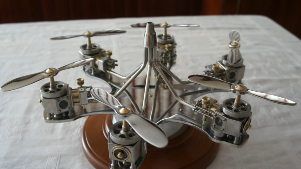
[Uri Tuchman] set out to do just that. Of course, cutting your own gears isn’t any fun if you didn’t also build the machine that does the cutting, right? And let’s be honest, what’s the point of making the machine in the first place if it doesn’t double as a work of art?
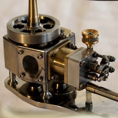
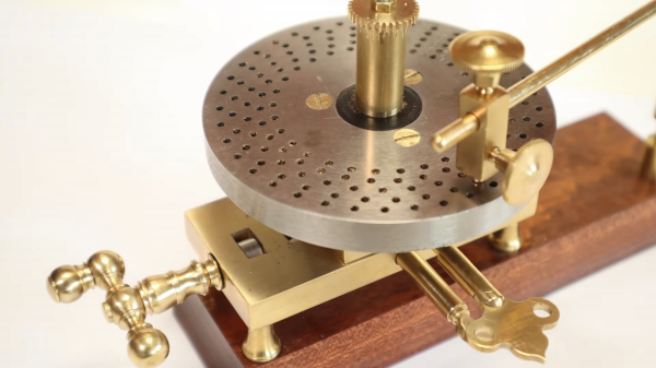
[Uri’s] machine, made from brass and wood, is simple in its premise. It is placed adjacent to a gear cutter, a spinning tool that cuts the correct involute profile that constitutes a gear tooth. The gear-to-be is mounted in the center, atop a hole-filled plate called the dividing plate. The dividing plate can be rotated about its center and translated along linear stages, and a pin drops into each hole on the plate as it moves to index the location of each gear tooth and lock the machine for cutting.
The most impressive part [Uri’s] machine is that it was made almost entirely with hand tools. The most advanced piece of equipment he used in the build is a lathe, and even for those operations he hand-held the cutting tool. The result is an elegant mechanism as beautiful as it is functional — one that would look at home on a workbench in the late 19th century.
[Thanks BaldPower]
Continue reading “Homemade Gear Cutting Indexer Blends Art With Engineering”
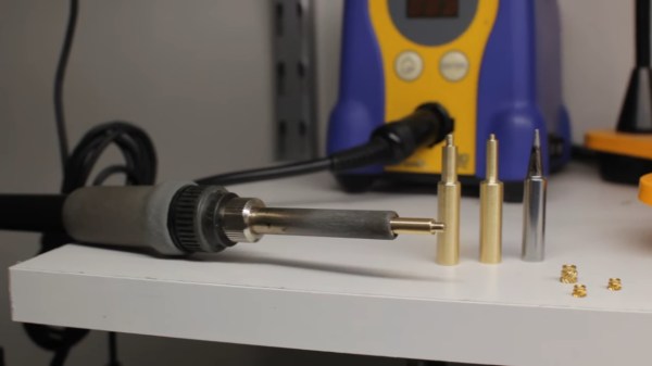
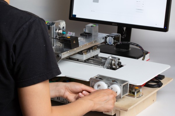
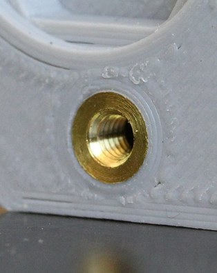 Like many of us, [Sean] has embraced the use of heat-set threaded inserts to beef up the mechanical connections on his 3D-printed parts. [Sean] dedicated a soldering iron to the task, equipping it with a tip especially for the job. But it was the flavor of iron proverbially known as a “fire stick” and he found that this iron was too hot for PLA prints. As the new owner of a lathe, he was able to make quick work of the job using a piece of brass rod stock. Luckily, Hakko tips just slip on the heating element, so no threading operations were needed. [Sean] made insert tips for multiple sized inserts, and the results speak for themselves.
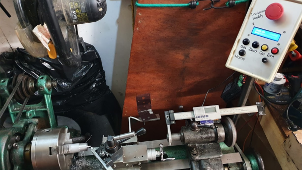
 [Tony Goacher] took this idea a few steps further when he created the